Continue to Site

Welcome to EDAboard.com

Welcome to our site! EDAboard.com is an international Electronics Discussion Forum focused on EDA software, circuits, schematics, books, theory, papers, asic, pld, 8051, DSP, Network, RF, Analog Design, PCB, Service Manuals... and a whole lot more! To participate you need to register. Registration is free. Click here to register now.

Reed relay multivibrator as a high frequency source?

Status
Not open for further replies.

neazoi

Advanced Member level 6
Joined
Jan 5, 2008
Messages
4,123
Helped
13
Reputation
26
Reaction score
15
Trophy points
1,318
Location
Greece
Activity points
36,955
Hello, I experiment with the possibility of using a miniature reed relay (PRMA1A05) as a source for high frequency generator (purely electromechanical).
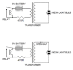
I have seen the next schematics in a website. The schematics are as in the website, the only addition I made was the addition of the resistor, to avoid sort circuit of the coil, when driving low impedance transformers, like toroids with low number of windings.

First I tried the first circuit. The transformer I used was a 1:1 toroid (because I did not need high voltage) taken out of a switched mode PSU. Instead of the neon bulb, I connected a 1Mohm digital storage scope. The fastest frequency I could get (self resonance of relay coil and transformer coils) was about 150KHz and that was the average frequency because the relay does not oscillate in constant frequency. Of course the relay cannot oscillate too much but I do not know how my scope frequency counter does the counting (resonances etc).

In the second circuit the author states that the spark gap increases the frequency. I have not yet tried it, but I was thinking to use a step-up transformer and a spark-gap like shown to generate high voltage. Then I could resonate this gap to a higher frequency using an LC. Maybe this will stabilize the frequency as well. I could use a HV transformer instead of a relay to generate the HV, the only reason I used the multivibrator scheme was to increase the output frequency (reed relays can oscilalte much faster than 50Hz). But if usung a spark-gap (https://en.wikipedia.org/wiki/Spark-gap_transmitter) an ordinary 50Hz HV transformer could be used?

Could I do something like this, would this work? The basic diagram of a spark-gap transmitter shows how this could work https://upload.wikimedia.org/wikipedia/commons/e/e6/Spark_gap_transmitter_diagram.png
Or any other proposed scheme?

My intention is to somehow generate a frequency signal (low power) on HF using electromechanical or transformer devices.
 

Attachments

  • circuit1.gif
    circuit1.gif
    4.1 KB · Views: 86
Last edited:

150KHz is extremely high for a mechanical oscillator! Bear in mind the number of lifetime open/close cycles specified by the relay manufacturer may be used up in a few seconds at that frequency.

I will warn you that although the circuit does work, it will be extremely unstable, possibly shifting several KHz within the space of a few seconds and the output waveform is just a series of spikes so it's harmonic content will be huge!

A similar technology was used to generate high voltage for powering vacuum tube equipment from 12V before transistors were around. The transformer typically stepped the voltage up to 150V for the HT supply. They were called 'vibrator' units, (not to be confused with other instruments of the same name!) and they were notoriously unreliable. The standard fix when the relay contacts stuck was to hit it with something hard. It was quite common to see power supplies with hammer marks all over them.

If you want to experiment with mechanical radio look at this web reference:
https://en.wikipedia.org/wiki/Varberg_Radio_Station

It would be relatively simple to recreate at home although I would suggest scaling it down a little! I have a DVD video about the transmitter, including 'live' operation scenes during one of it's annual tests.

Brian.

Yes I have seen this video, it's awesome!
That is what I was thought, the counter measures some of the harmonics. And these dumped spikes you refer move continuously close of apart like an accordion, which indicates that the frequency is far from being stable!
Maybe as a high voltage generator it would be more suitable.

I experimented in the past with magnetic amplifiers, but to operate them at HF you need an AC source more than double the output frequency. It is this AC source that I am trying to generate using other means than semiconductors and tubes.

As far as I can see a spark gap transmitter could do that, although the output is a damped sine wave.

I am not aware of any other methods that one could use for this frequency generation.
Any comments or ideas would be highly appreciated.
 

The Varberg method is a basic AC generator made from a wheel with lots of magnets around it's circumference, each magnet induces a voltage as it passes a pick-up coil. It is the diameter of the wheel and the number of magnets around it that determines the frequency per revolution. The mass of the wheel provides stability against short term drift and the gear ratio and speed of the motor determines the frequency. The beauty of the system is produces a clean sine wave output, almost ready for transmitting, it drawback is the sheer size of the wheel.

You could scale it down, a small motor could be driven to say 5,000 RPM then used to drive a gearbox to increase the speed of the 'transmit' wheel. If made large enough you could probably fit enough magnets around it to produce a few tens of KHz quite easily.

Another thought if you don't mind mixing some 'hi tech' with the mechanical bits is to do it optically. You can spin a graticuled disk between a light source and one or more sensors so the beam is interrupted many times per motor revolution. A similar system to that used in a ball mouse and in printers to read the print head position. It can give many more cycles of output (and still relatively pure signal) than the magnetic method. You can even amplitude modulate the resulting signal by varying the light intensity.

I remember many years ago someone took two photographs of a checkerboard pattern table cloth and used the negatives as a modulation source. They framed the negatives to keep them flat and attached one to the cone of a loudspeaker, the other to the edge of the lousdspeaker. when light was shone through them the amount passing through depended on the alignment of the negatives so sound sent to the loudspeaker modulated the light intensity! Clever but not very practical!

Brian.
 

A reed switch is good at creating a low resistance step voltage and into an inductive load, a ramp current limited by the current from the net series resitance.

Step function is the integral of an impulse and conversely the derivative gets you back to an impulse.

The spectral response of an impulse to a load is defined by it's transfer function. All inductors have capacitance and air coils have the least capacitance yet the lowest relativity permeability =1.

To create broad spectral noise, from an impulse, an ionizing gap has the fastest breakdown due to the "avalanche" effect in any gas be it air or argon or petrol.

The current rise time of DC discharge is only limited by the inductance in the current loop and peak current limited by the loop resistance when shorted.

Similarly when an inductor is charged with current and switched open, the rate of voltage rise dv/dt is limited by the stray capacitance.
I=C dv/dt

When the reed switch opens a high voltage is created which breaks down at approximately 1kV/mm for a small contact area with rise times that will be < 1 ns but cannot be measured without 50 Ohm Scopes with a bandwidth > 300 MHz. Even 10 ps is possible.

This was the principle for which the first broadcasts of Morse Code operated on utilizing the impulse stimulus and the transfer function of the resonant antenna, which Tesla demonstrated and later Marconi.
 
  • Like
Reactions: neazoi

    neazoi

    Points: 2
    Helpful Answer Positive Rating
I distinctly remember a design in one of the UK ham magazines back in the day for a LF transmitter using a stepper motor as the alternator, driven by a syncronous motor, with frequency multiplication by saturatable reactors (Ferrite core transformers arranged to be carrying a fair amount of DC to offset the B/H curve).

Lets see, 200 steps per rev * 50 revs/second = 10KHz at the output of the 'alternator', but we have two phases so maybe more like 20KHz (Use a saturatable reactor as a mixer!), a second saturatable reactor as a harmonic generator and you are into the long wave band.

Use a DC servo motor instead of the syncronous drive and you have a tunable sender, key the DC bias to one of the saturatable reactors and you can send a message.

I keep meaning to build such a rig and then apply for a notice of variation to get permission to try for a QSO with Varburg sometime.

73 M0HCN.
 

To create broad spectral noise, from an impulse, an ionizing gap has the fastest breakdown due to the "avalanche" effect in any gas be it air or argon or petrol.

This is an important thing. So the spark creates a wideband noise, which is then limited by tuned circuits with increased Q such as loosely coupled transformers, to narrow it's bandwidth. Maybe I could use this technique, which was well known once upon a time. The only thing is that the output wave out of a spask gap transmitter is dumped.
I have read in a paper that the first generation of spark gap transmitters used an induction coil connected directly to the antenna without a capacitor discharge cycle. This was very dangerous but induced a continuous current to the antenna, although only tiny powers could be achieved. Maybe this is the key for continuous wave, since no antenna operation will be done, but it will be used as a signal generator?
Or maybe I simply misunderstood the paper.
 

For a (sort of) continious wave from a 'spark' transmitter google the 'Poulsen arc transmitter'.

Regards, Dan.
 
  • Like
Reactions: neazoi

    neazoi

    Points: 2
    Helpful Answer Positive Rating
Status
Not open for further replies.

Similar threads

Part and Inventory Search

Welcome to EDABoard.com

Sponsor

Back
Top