username99MD
Newbie level 2
- Joined
- Jan 14, 2014
- Messages
- 2
- Helped
- 0
- Reputation
- 0
- Reaction score
- 0
- Trophy points
- 1
- Location
- Western Europe
- Activity points
- 16
As the title suggests I need some help understanding a circuit I built in college last semester.
It is a reaction timer that counts the time it takes a user to react to the LEDs when they start to count.
When the user stops the timer, the time of reaction is displayed. This is then cleared, when the user resets the LEDs, the LEDs display '000'.
As I said I built this 'Reaction Time Circuit' last semester, it was basically meant to get us going soldering and planning out the layout of components on the board. The schematic was already provided for me.
I completed the project but never understood how it worked, now I want to figure it out, and Digital was not my strongest point so I thought I would enlist the help of you guys.
As I am new here if you think this question would be better suited to a more appropriate forum could you please suggest this to the moderator.
Otherwise I look forward to seeing your replies.
Thankyou
- - - Updated - - -
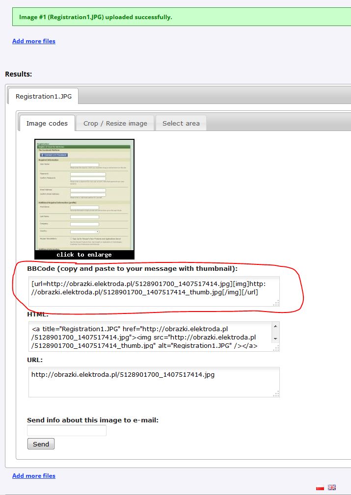
I can't figure out to upload the schematics and picture, can you advise me on the steps to tak
When I click 'add and image' below I get brought to a new tab that does not appear like this webpage. I seem to be able to upload pictures here but then I just get this warning 'bad e-mail address', I click 'ok' and then nothing happens..
Any advice?
It is a reaction timer that counts the time it takes a user to react to the LEDs when they start to count.
When the user stops the timer, the time of reaction is displayed. This is then cleared, when the user resets the LEDs, the LEDs display '000'.
As I said I built this 'Reaction Time Circuit' last semester, it was basically meant to get us going soldering and planning out the layout of components on the board. The schematic was already provided for me.
I completed the project but never understood how it worked, now I want to figure it out, and Digital was not my strongest point so I thought I would enlist the help of you guys.
As I am new here if you think this question would be better suited to a more appropriate forum could you please suggest this to the moderator.
Otherwise I look forward to seeing your replies.
Thankyou
- - - Updated - - -
I can't figure out to upload the schematics and picture, can you advise me on the steps to tak
When I click 'add and image' below I get brought to a new tab that does not appear like this webpage. I seem to be able to upload pictures here but then I just get this warning 'bad e-mail address', I click 'ok' and then nothing happens..
Any advice?