Continue to Site

Welcome to EDAboard.com

Welcome to our site! EDAboard.com is an international Electronics Discussion Forum focused on EDA software, circuits, schematics, books, theory, papers, asic, pld, 8051, DSP, Network, RF, Analog Design, PCB, Service Manuals... and a whole lot more! To participate you need to register. Registration is free. Click here to register now.

[SOLVED] 20x4 LCD not working with Pic18..Need Help.....

Status
Not open for further replies.

Praveen Kumar P S

Member level 4
Joined
Aug 21, 2014
Messages
79
Helped
1
Reputation
2
Reaction score
1
Trophy points
8
Location
India
Activity points
627
Hello Guys.........

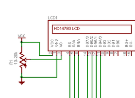
I connected my 4x20 lcd to pic18f4550..But it not even displaying a character.....i used a 10k pot for contrast....The Backlight is working fine....i used 4 lcd pin for data (D4-D7) , Remaining data pins (D0-D3) are left alone...I dont know why it is not working ....

Plz Help me Guys.............
 

Hi,

You do not mention the RS E and RW pins which control the data flow ?

If you are building your own circuit double check all the connections; poor wiring / soldering to the lcd is a very common fault.

If thats all ok, as said above post your code and circuit.

Does your lcd display 'black' boxes when powered on and the contrast turned up ?
 

Hey guys....
Here is my code......

Code:
#include <18f4550.h>
#fuses NOWDT,NOPROTECT,NOLVP,NODEBUG,NOPBADEN,PUT,HS,BROWNOUT
#use delay(clock=48000000)           
#include <flex_lcd416.c>
#define Hs PIN_A1
void main()                                        
{ 
 lcd_init(); 
while(1)
   {                  
    lcd_setcursor_vb(1,1);
    Delay_ms(10);
    lcd_gotoxy(3,1);
    lcd_putc("EMBEDDED LAB!");                          
    delay_ms(10);
    output_bit(Hs,1);
    delay_ms(100);
    output_bit(Hs,0);
    delay_ms(100);
    
   }
    
}


Here my connection...........

7428272900_1410532161.png


When Power on, Black Box Appear for 5 sec then it disappears ............

I m using Flex_lcd.h
B0,B1,B2 connected to D0,D1,D2 of LCD Respectively
B4,B5,B6,B7 connected to D4,D5,D6,D7 of LcD Respectively....
BackLight appears to be fine..........
Plz Help me guys
Thank You....
 
Last edited:

Post the complete CCS C code. Show the LCD defines.
 

Guys i m having a problem .....
i tried to run a code for lcd blinking ....the code is given below....

Code:
#include <18f4550.h>
#use delay(clock=40000000)
#fuses NOWDT, PUT, NOPROTECT, BROWNOUT, NOMCLR, NOLVP, NOCPD, INTRC
void main(void)
{
 
 for(;;)
 {
  output_low(PIN_A0);
  delay_ms(30);
  output_high(PIN_A0);
  delay_ms(30);
 }
}

But its not working....PIN_A0 is giving voltage of 0.65 V....I think my Pic is damaged....8-O

i think i have given a 5V supplay to PIN_A0 ,carelessly ..which ruined my pic....

also i doubt the fuse i have used....

Plz help me guys.....

Thank YOU
 
Last edited:

Your fuse settings is correct. Try another pin instead of A0. 30 ms delay is too small. Increase it to 500 ms.
 

Your fuse settings is correct. Try another pin instead of A0. 30 ms delay is too small. Increase it to 500 ms.

I did that milan....
But no pins in ANY PORT is giving me voltage above 1V..Execpt pin B7....
I think i have to buy new pic................
 

You haven't used HS PLL but you are using 40 MHz Clock. I don't know whether it works or not. Please zip and post your CCS C project files. I will test it here.
 

You haven't used HS PLL but you are using 40 MHz Clock. I don't know whether it works or not. Please zip and post your CCS C project files. I will test it here.

Here is the project which i was using for led blink.......

Thank You...........
 

Attachments

  • Short code lcd.rar
    38.9 KB · Views: 88

Mr praveen

Even though your are are using flel


Code:
#include <18f4550.h>
#fuses NOWDT,NOPROTECT,NOLVP,NODEBUG,NOPBADEN,PUT,HS,BROWNOUT
#use delay(clock=48000000)           
#include <flex_lcd416.c>////////////////[COLOR="#FF0000"]this is the problem eventough are using flex lcd driver it is only for 16x4 [/COLOR] [COLOR="#00FF00"]there is a driver  named lcd420.c in ccs compiler by default it will not enable change it to #include<lcd420>  [/COLOR]
#define Hs PIN_A1
void main()                                        
{ 
 lcd_init(); 
while(1)
   {                  
    lcd_setcursor_vb(1,1);
    Delay_ms(10);
    lcd_gotoxy(3,1);
    lcd_putc("EMBEDDED LAB!");                          
    delay_ms(10);
    output_bit(Hs,1);
    delay_ms(100);
    output_bit(Hs,0);
    delay_ms(100);
    
   }
    
}
 
Last edited by a moderator:

Code:
#use delay(clock=40000000)
#fuses XT, NOWDT, NOPROTECT, BROWNOUT, PUT, NOLVP

you need to add fuse for high speed crystal.
for(;;)
{
output_bit(PK,1);
Output_high_A(0Xff);
Output_high_B(0Xff);
Output_high_C(0Xff);
Output_high_D(0Xff);
}

set port A,B,C,D as output before you use "Output_high_x()".
 

Status
Not open for further replies.

Similar threads

Part and Inventory Search

Welcome to EDABoard.com

Sponsor

Back
Top