Continue to Site

Welcome to EDAboard.com

Welcome to our site! EDAboard.com is an international Electronics Discussion Forum focused on EDA software, circuits, schematics, books, theory, papers, asic, pld, 8051, DSP, Network, RF, Analog Design, PCB, Service Manuals... and a whole lot more! To participate you need to register. Registration is free. Click here to register now.

[SOLVED] Ac Sweep for a single frequency

Status
Not open for further replies.

ehsantech

Member level 3
Joined
Jul 29, 2014
Messages
67
Helped
0
Reputation
0
Reaction score
0
Trophy points
6
Activity points
492
Hello
here is my program and settings
**broken link removed**
As you see the simulation settings I want to see voltage output of each nodes @60Hz.but here is my output file information:

**** INCLUDING SCHEMATIC1.net ****
* source PHASORE
R_R1 N00149 N00092 1k
L_L1 N00092 N00096 2mH
C_C1 N00096 0 3uf
V_V1 N00149 0 DC 0Vdc AC 4Vac 10

**** RESUMING wow2.cir ****
.END

**** SMALL SIGNAL BIAS SOLUTION TEMPERATURE = 27.000 DEG C

***************************************************************************
NODE VOLTAGE NODE VOLTAGE NODE VOLTAGE NODE VOLTAGE

(N00092) 0.0000 (N00096) 0.0000 (N00149) 0.0000


VOLTAGE SOURCE CURRENTS
NAME CURRENT

V_V1 0.000E+00

TOTAL POWER DISSIPATION 0.00E+00 WATTS

but I got voltage of each node zero.
what is my mistake?
 

hi,
An AC sweep requires a Start/Finish frequency which are not the same value, also more than one point.

For a fixed frequency use a Time sweep, with V1 set to 60Hz.

E
 

Hi,

... maybe the voltage readings are DC readings.
Try to use RMS redaings.
Or use a scope.


Klaus
 

Thanks for you replay
could you tell me how can see Ac voltage such as Dc voltage on schematic simulation?or how can see the Stady state ac voltage?
Thanks
 

Pspice RLC AC analysis

Hello
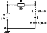
here is my pspice code and circuit that I want to simulate.
index.png

Code:
Hello the world
V 1 0 AC 1V
R 1 2 50
L 2 3 .02H
C 3 0 150nf
.ac LIN 4901 100Hz 5kHz
.Probe
.END

as you see the probe windows we have this output(Resistor current and Capacitor voltage)
Cap.JPG
Res.JPG

So we do some calculation
|I|=.02 in resonance frequency (2.9Khz)
|Xc|=1/(2900*150*10^(-9))=2298.8
|Vc|=|I|*|Xc|=.02*2298.8=45.97

but according the V(3)(Capacitor voltage) we have 7.3 at resonance frequency.
other calculation:
we know the Capacitor voltage at resonance frequency is about |VC|=Q*|Vin |

|Vc|=|I|*|Xc|=(|Vin|/R)(1/w0C)=|Vin|*Qc

w0=2900hz
QL=(w0*L)/(R)=1.16
|VC|=Qin*|Vin=1.16*1=1.16

Or

w0=2900hz
QC=(1)/(w0CR)=45.97
|VC|=Qin*|Vin=45.97*1=45.94


If there is no problem could you tell me what are my mistakes?

- - - Updated - - -

Sorry I found my problem
I didn't substitute the resonance frequency into w=2*Pi*F
 

Status
Not open for further replies.

Part and Inventory Search

Welcome to EDABoard.com

Sponsor

Back
Top