Continue to Site

Welcome to EDAboard.com

Welcome to our site! EDAboard.com is an international Electronics Discussion Forum focused on EDA software, circuits, schematics, books, theory, papers, asic, pld, 8051, DSP, Network, RF, Analog Design, PCB, Service Manuals... and a whole lot more! To participate you need to register. Registration is free. Click here to register now.

Variable speed drive circuit for fan is OK?

Status
Not open for further replies.
T

treez

Guest
Hello,

Please could you check the attached fan drive circuit for driving the "ebm papst 8218 JH3" fan? Please advise if this circuit is OK?

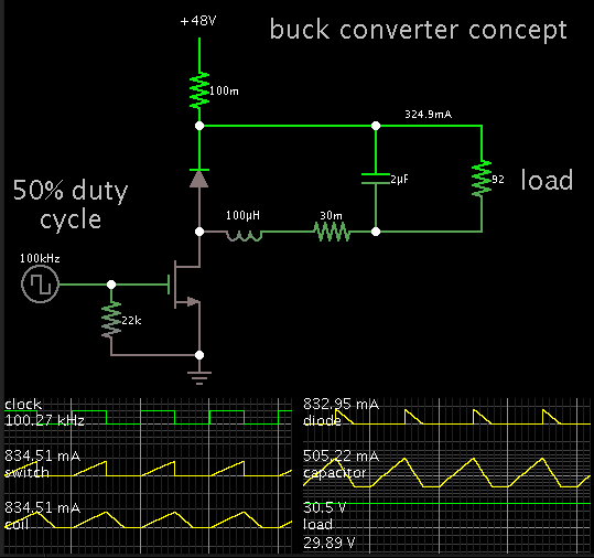
Basically, as you may see, it is driving the fan from a Buck converter.
Do you believe that the 10uF capacitor across the fan is enough capacitance?
The PWM is at a frequency of 100KHz, and its duty is variable by a microcontroller.

Please could you also supply the coil inductance of the fan?

Fan datasheet:
**broken link removed**

Fan series datasheet:
**broken link removed**
 

Attachments

  • Fan drive circuit.pdf
    13.7 KB · Views: 50
Last edited by a moderator:

25W draw at 48V. The fan load calculates to be 92 ohms.

The 100 uH coil will work okay with 100 kHz.

You could reduce the cap value to 2 uF, and ripple would be just a few percent.

However the cap must carry bursts of several hundred mA per cycle. So you may want to use a gang of them.
 
  • Like
Reactions: treez

    T

    Points: 2
    Helpful Answer Positive Rating
These "bursts" that you speak of, are they from the termination of the fan dead time? (its a bldc sop will have dead time)
We are worried about overheating the fan with high frequency ripple current , and fear we may get this if the cap is less than 100u?
 

The originally chosen 10 µF capacitor looks reasonable to me. Recent ceramic capacitors (MLCC) have very low ESR and can carry several A ripple current without problems.
 
  • Like
Reactions: treez

    T

    Points: 2
    Helpful Answer Positive Rating
These "bursts" that you speak of, are they from the termination of the fan dead time? (its a bldc sop will have dead time)
We are worried about overheating the fan with high frequency ripple current , and fear we may get this if the cap is less than 100u?

The bursts are the regular triangular waveform occurring each cycle.

This simulation shows how your schematic behaves (theoretically) with an unchanging resistive load.

The fan will probably draw power differently. Perhaps not in a steady stream. So a greater capacitor value could be appropriate.

 
  • Like
Reactions: treez

    T

    Points: 2
    Helpful Answer Positive Rating
The fan series datasheet (2nd link in top post) says that this fan has a "PWM control input" but gives no explanation of it. Does anyone know what it is?

- - - Updated - - -

The originally chosen 10 µF capacitor looks reasonable to me. Recent ceramic capacitors (MLCC) have very low ESR and can carry several A ripple current without problems.

Do you know what the ripple current would be in the 10u?
 

The fan series datasheet (2nd link in top post) says that this fan has a "PWM control input" but gives no explanation of it. Does anyone know what it is?
It's described in a document. I'm not sure if 8218 JH3 has the option.
https://www.ebmpapst.com/media/cont...ctfanssingle2011/DC_fans_-specials_2014_n.pdf
Do you know what the ripple current would be in the 10u?
No. It can be calculated.

- - - Updated - - -

The 8200 J catalog page says "also available with PWM option"
 

The fan series datasheet (2nd link in top post) says that this fan has a "PWM control input" but gives no explanation of it. Does anyone know what it is?

This suggests that you do not need the buck converter to step down the 48V. You may be able to pulse the fan instead. I could be wrong. I don't know how a brushless motor will respond to a pwm supply.

There are fans with 2 leads (supply and ground).
There are fans with 3 leads, with the third being a speed control wire.

Do you know what the ripple current would be in the 10u?

My simulation shows output ripple voltage is now less than 1%. This is at an arbitrary 50 percent duty cycle.

Again, I'm using a resistive load. I cannot be sure how the fan draws power.
 

Status
Not open for further replies.

Similar threads

Part and Inventory Search

Welcome to EDABoard.com

Sponsor

Back
Top