Continue to Site

Welcome to EDAboard.com

Welcome to our site! EDAboard.com is an international Electronics Discussion Forum focused on EDA software, circuits, schematics, books, theory, papers, asic, pld, 8051, DSP, Network, RF, Analog Design, PCB, Service Manuals... and a whole lot more! To participate you need to register. Registration is free. Click here to register now.

Unipolar 2 phase Stepper motor Burn

Status
Not open for further replies.

wolf12

Advanced Member level 4
Joined
Mar 31, 2011
Messages
109
Helped
1
Reputation
2
Reaction score
1
Trophy points
1,298
Activity points
2,102
I'm trying to test following unipolar 2 phase stepper motor,
http://www.nidec-servo.com/en/digital/pdf/KH42K.pdf

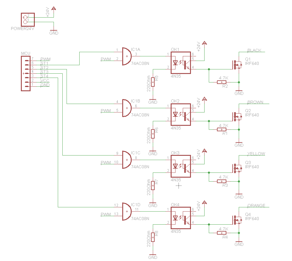
I made a stepper motor driver with IRF640 mosfets and opto couplers for use with arduino,

I think of two possible causes,
1. I miswired the end points of the stepper motor
2. I was not using PWM or Resistors to limit the current to the motor and it was directly connected to 24V though mosfets,

which one is the cause?
If 'not using PWM' is the cause, can you tell me which duty and frequency should I use? And please suggest any additional protection for the motor.

Thank you.
 

Wait. YOU are asking US if you miswired your circuit? And how, exactly, would you expect us to determine that?

But forgetting that for a moment, you need to control the average current to your motor windings. I think you need to learn something about driving stepper motors, PWM, feedback and such.

Just using basic electronic theory: you've got a motor with a 3.1 ohm resistance, and a rated current of 1.2 amps. But you've connected it to 24 volts, which will give you almost 8 amps. Not good.

For PWM usually (but not always), there is a current-sense resistor that develops a voltage that is fed back to your controller which determines the pulse width.

There are several factors that determine the frequency. Generally, you want a frequency higher than 20KHz, so you can't hear it. But the higher the frequency, the higher the power losses. You also need to consider the motor inductance.

Here's a start, but I seriously suggest you educate yourself a bit before you go further.

**broken link removed**
 
  • Like
Reactions: wolf12

    wolf12

    Points: 2
    Helpful Answer Positive Rating
Thank you for the reply and Sorry for misunderstanding, I know that I miswired, because arduino stepper library and my stepper motor signals in datasheet were different. But I didn't know that miswire can cause a stepper motor to burn. Now I understand 8 amp is the problem.

My stepper motor driver circuit is like following with IRF640 mosfet, except I use opto coupler for Arduino interface.
https://1.bp.blogspot.com/-Xn6kyI4EcFw/TmvHjwL0QOI/AAAAAAAAA0E/qCsSMWxHeXk/s1600/Unipolar_BD.jpg

So should I connect shunt resistor to source of mosfets? Or can I make the circuit without current sensor for now, with very low duty? Because my project is not about designing efficient motor driver. But I want to avoid burning the motor.

I know a PWM motor driver IC used for this motor, SLA7026 but I can't find it where I live. Looking for similar driver with my lack of knowledge in PWM stepper motor is difficult. I will study the note you provided.

Thank you.

Wait. YOU are asking US if you miswired your circuit? And how, exactly, would you expect us to determine that?

But forgetting that for a moment, you need to control the average current to your motor windings. I think you need to learn something about driving stepper motors, PWM, feedback and such.

Just using basic electronic theory: you've got a motor with a 3.1 ohm resistance, and a rated current of 1.2 amps. But you've connected it to 24 volts, which will give you almost 8 amps. Not good.

For PWM usually (but not always), there is a current-sense resistor that develops a voltage that is fed back to your controller which determines the pulse width.

There are several factors that determine the frequency. Generally, you want a frequency higher than 20KHz, so you can't hear it. But the higher the frequency, the higher the power losses. You also need to consider the motor inductance.

Here's a start, but I seriously suggest you educate yourself a bit before you go further.

**broken link removed**
 

If you want to use a resistor, you don't want a SHUNT, you want a SERIES resistor. And you don't want it in the source, you want it in the drain. And it would have to be 17 ohms, 25 Watts. That is a BIG resistor.

If you want to use simple PWM, then you would need a duty cycle of about 15%. (.15x 24/3.1)=1.2AMPS.
 
  • Like
Reactions: wolf12

    wolf12

    Points: 2
    Helpful Answer Positive Rating
Thanks a lot. I'll try that.

If you want to use a resistor, you don't want a SHUNT, you want a SERIES resistor. And you don't want it in the source, you want it in the drain. And it would have to be 17 ohms, 25 Watts. That is a BIG resistor.

If you want to use simple PWM, then you would need a duty cycle of about 15%. (.15x 24/3.1)=1.2AMPS.
 

I tested with 15% duty, The motor torque is very low. Same motor used in a device original motor driver board and has very high torque.
I use full step sequence.

Arduino library has only 500Hz PWM, can this be the problem?

Also the motor vibrates, but I think its because the frequency is low.
 

What's your step rate? Unless it's pretty slow low, that 500Hz PWM frequency might be too low. For example, if you want a 10% duty cycle, the PWM frequency will need to be at least 10 times your step rate.
 
  • Like
Reactions: wolf12

    wolf12

    Points: 2
    Helpful Answer Positive Rating
Thank you. You are correct, I changed Arduino registers to output 31 kHz and I got the torque I wanted.

I notice one mosfet heats up more than the other 3. I replaced the mosfet but still same. Do you have have any idea why would that be ?
 

I would say: look at the signals with a scope. Without a schematic or some signal information, it's hard to speculate. Does it get a LOT hotter than the other 3?
 
  • Like
Reactions: wolf12

    wolf12

    Points: 2
    Helpful Answer Positive Rating
Yes, one mosfet is a lot hotter than the others (Q3),
Step sequence 1010 0110 0101 1001

I attached a schematic


Thank you.
 

1) It's wired wrong
2) You've got a shorted motor phase
3) You're dwelling too long on one state (where Q3 is on)

- - - Updated - - -

1) It's wired wrong
2) You've got a shorted motor phase
3) You're dwelling too long on one state (where Q3 is on)

I just looked at this again. You're putting 24 volts on the gate of the IRF640! Maximum is 20V!!!; normally you only need about 10-12 volts.
 
  • Like
Reactions: wolf12

    wolf12

    Points: 2
    Helpful Answer Positive Rating
1) It's wired wrong
2) You've got a shorted motor phase
3) You're dwelling too long on one state (where Q3 is on)

- - - Updated - - -

1) It's wired wrong
2) You've got a shorted motor phase
3) You're dwelling too long on one state (where Q3 is on)

I just looked at this again. You're putting 24 volts on the gate of the IRF640! Maximum is 20V!!!; normally you only need about 10-12 volts.

Thank you. I adjusted gate voltage to 14V. And this time I wired 1.2Amp fuses to each phase and set duty around 7% and now I keep burning fuses in less than a second. Maybe the stall current is high or I wired it wrong again. Previously I managed to run the circuit with limiting total current in to circuit 2.4Amp, But now I keep burning that fuses too.

I checked the motor phases, winding resistance is correct.
I have to wait till Monday to work on it again.

Does this motor require microsteppting for smooth and low noise operation?
 

I think you need to step back and read the data sheet.

1) Winding current is 1.2 amps, not 2.4
2) The winding resistance is 3 ohms. With 24 volts, that means you can draw 8 amps if you don't limit the current with PROPER pwm or a resistor.

If you have an oscilloscope, you should look at your signals.

Microstepping will give you lower noise, but your application will determine if you really need it or not.
 
  • Like
Reactions: wolf12

    wolf12

    Points: 2
    Helpful Answer Positive Rating
I thought two phases are on at a time in full step sequence so, total current in to the circuit would be 2.4 Amp.

I will check with oscilloscope.

Thank you.

I think you need to step back and read the data sheet.

1) Winding current is 1.2 amps, not 2.4
2) The winding resistance is 3 ohms. With 24 volts, that means you can draw 8 amps if you don't limit the current with PROPER pwm or a resistor.

If you have an oscilloscope, you should look at your signals.

Microstepping will give you lower noise, but your application will determine if you really need it or not.
 

I thought two phases are on at a time in full step sequence so, total current in to the circuit would be 2.4 Amp.

I will check with oscilloscope.

Thank you.

Regardless, it's still 1.2 amps per phase, not 2.4.

You better check your sequencing and your pwm.
 

Status
Not open for further replies.

Part and Inventory Search

Welcome to EDABoard.com

Sponsor

Back
Top