Continue to Site

Welcome to EDAboard.com

Welcome to our site! EDAboard.com is an international Electronics Discussion Forum focused on EDA software, circuits, schematics, books, theory, papers, asic, pld, 8051, DSP, Network, RF, Analog Design, PCB, Service Manuals... and a whole lot more! To participate you need to register. Registration is free. Click here to register now.

[SOLVED] Driving the Inverter Transformer?

Status
Not open for further replies.

sghr220

Junior Member level 3
Joined
Jun 2, 2009
Messages
31
Helped
1
Reputation
2
Reaction score
1
Trophy points
1,288
Activity points
1,512
Hi all,

I am in the process of designing a DC to 220v AC / 50 Hz pure sine-wave inverter which is very unoriginal of course :smile:.

Thanks to Tahmid's blog and all the great threads in this forum i collected a wealth of information about this application. Having some unanswered questions, i hope you can help me with them so here we go...

The transformer i am planning to use is a 50 Hz iron core which doesn't have a center tap so i have to use either a half-bridge or a full bridge configuration. The bridge is to be constructed using N-Mosfet's so we have a high and low sides.

Some photos from Tahmid's blog...

push-pullgeneratedcircuit_zps51b18d01.png


The push-bull configuration is the simplest in driving and requires a few transistors to implement but it also requires a center tapped transformer (and also there is the efficiency limitations).


full-bridgegeneratedcircuit_zps634e54b2.png


The full-bridge configuration is also pretty straight forward but requires double the number of transistors to achieve a certain output power.


half-bridgegeneratedcircuit_zpscd46448f.png


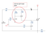
And here is the half-bridge circuit which has (i guess) the best of both worlds less transistors and no center tap required but i can't quite understand the operation of the circuit and what are the function of the two 330uF capacitors connected to the second coil terminal?​


I am not using a HV bus in this inverter, the battery voltage is fed to the transformer driving circuit directly. The battery voltage can be 12v, 24v, 36v and 48 volts according to the inverter output power in order to get some reasonable battery current and not several hundreds of amps that will fry the battery in the shortest time frame. :smile:

Another question will be the ratio of the transformer, my basic understanding is that for a single 12v battery we need a 12-0-12 center-tapped transformer or a 0-12 transformer, but in some of the circuit i see a 8-0-8 and 10-0-10 transformers used to produce a 220v output why is that? and is the ratio of the transformer dependent on the inverter output waveform? and if so how to calculate the ratio for a modified sine-wave inverter and for a pure sine-wave inverter fed from a 12v battery?
 

The capacitors are to prevent any DC current in the primary due to slight duty-cycle differences between the two drivers and to provide a source of current through the transformer when the bottom driver MOSFET is on.

The transformer ratio does depend on the waveform. For example, a pure sine-wave driver would have a peak generated voltage of 12V with a 12V battery, giving a maximum RMS voltage of about 8.4V. Thus to convert that to a 220V RMS output would require an 8V:220V transformer. If the waveform is a modified sine-wave then you need to determine the RMS value of that to calculate the proper turns ratio needed.

Actually your bottom circuit has only a peak voltage of 6V (12Vpp) applied across the winding because the capacitor will charge up to 1/2 the supply voltage, so you would need a 4V:220V transformer and your primary current would double. That's the advantage of a full-bridge, it provides the full peak voltage of the battery across the transformer primary giving double that for the PP voltage and reducing the current.
 

Thank you for the detailed reply,

The transformer ratio does depend on the waveform. For example, a pure sine-wave driver would have a peak generated voltage of 12V with a 12V battery, giving a maximum RMS voltage of about 8.4V. Thus to convert that to a 220V RMS output would require an 8V:220V transformer. If the waveform is a modified sine-wave then you need to determine the RMS value of that to calculate the proper turns ratio needed.

This wikipedia page states that for a modified square wave the RMS value is the same as sine-wave which equals: Peak/0.707.So can the same turns ratio be used for both waveforms?
https://en.wikipedia.org/wiki/Root_mean_square
 

I dont quite get the idea of 12V translating to 8.4V. If you expand the square wave on the Fourier series, it will become apparent at once that the peak value of the fundamental component is 1.27*12 = 15.25V. This will have an RMS value of 12.35V and not 8.4V
 

I dont quite get the idea of 12V translating to 8.4V. If you expand the square wave on the Fourier series, it will become apparent at once that the peak value of the fundamental component is 1.27*12 = 15.25V. This will have an RMS value of 12.35V and not 8.4V

Do you mean to say that it's a more efficient waveform in terms of the transformer ratio?
 

Efficiency is not defined in terms of amplitude. But if you are speaking of efficiency of turn ratio... well then it may be true.
A sine wave has a large portion trimmed, on the other hand a square wave does not.
 

driver_stage_zps6f17d6bf.gif

In the circuit above (which i am sure you've seen it before) the Mosfets are all n-channel and yet the circuit uses a transformer without a center tap, how is that done? what is the method for driving the high side? Are C15 and C17 bootstrap capacitors?

- - - Updated - - -

Efficiency is not defined in terms of amplitude. But if you are speaking of efficiency of turn ratio... well then it may be true.
A sine wave has a large portion trimmed, on the other hand a square wave does not.

So for a 12v input voltage what do you think the appropriate turns ratio for the two types of inverters: the pure sine and the modified sine?

Thanks in advance.
 

Why would you even require a center tap in a H Bridge topology?
The driver uses discrete components. I had built a similar one a few months ago, see the attachment..
Yes, C15 and C17 are bootstraps

- - - Updated - - -

But instead of localized NPN switching, a totem pole is used in your circuit

- - - Updated - - -

For a 12/230V transformer, 1:25 to 1:27 should be ok, considering drop across the leakage and lower voltage (10.5) during partial discharge of battery
 

Attachments

  • Capture3.PNG
    Capture3.PNG
    35.9 KB · Views: 76

This wikipedia page states that for a modified square wave the RMS value is the same as sine-wave which equals: Peak/0.707.So can the same turns ratio be used for both waveforms?
https://en.wikipedia.org/wiki/Root_mean_square
That would appear to be a true statement.

- - - Updated - - -

I dont quite get the idea of 12V translating to 8.4V. If you expand the square wave on the Fourier series, it will become apparent at once that the peak value of the fundamental component is 1.27*12 = 15.25V. This will have an RMS value of 12.35V and not 8.4V
A sine-wave or modified sine-wave converter was the subject of this thread. How did a square-wave converter get into the discussion?
 

A sine-wave or modified sine-wave converter was the subject of this thread. How did a square-wave converter get into the discussion?
The circuits in post #1 which are all DC/DC converters will surely use square-wave. But we don't know about the intended inverter waveform.
 

The circuits in post #1 which are all DC/DC converters will surely use square-wave. But we don't know about the intended inverter waveform.
Well, the op stated he was working on a pure sine-wave inverter so it would seem that the square-wave would have a sine-wave PWM modulation to give a (nearly) pure sine-wave at the transformer output.
 

The circuits in post #1 which are all DC/DC converters will surely use square-wave. But we don't know about the intended inverter waveform.

The circuits in the first post was used only to demonstrate the use of push-pull, half-bridge and full-bridge circuits used to drive the transformer and i stated in the first post that i am using a 50 Hz iron core transformer and a single stage converter i.e no high voltage bus.

Thanks for the reply.
 

Well, the op stated he was working on a pure sine-wave inverter so it would seem that the square-wave would have a sine-wave PWM modulation to give a (nearly) pure sine-wave at the transformer output.
May be. In this case, the windings ratio must been chosen to generate the sine peak voltage (325 V) at the secondary.
 

The circuits in the first post was used only to demonstrate the use of push-pull, half-bridge and full-bridge circuits used to drive the transformer and i stated in the first post that i am using a 50 Hz iron core transformer and a single stage converter i.e no high voltage bus.
But the question is about the "pure" sinewave. How are you generating that?
 

May be. In this case, the windings ratio must been chosen to generate the sine peak voltage (325 V) at the secondary.

I guess you're right so for a 12v battery, a transformer without the center tap and an H-bridge driving that the voltage ratio should be 12:325. Is that correct? (so similar to 8.5:230:))

- - - Updated - - -

But the question is about the "pure" sinewave. How are you generating that?

Pic microcontroller using SPWM.
 

I guess you're right so for a 12v battery, a transformer without the center tap and an H-bridge driving that the voltage ratio should be 12:325.
Assuming ideal transformer and switches. The step-up ratio must be additionally increased to compensate for real circuit behavior.
 

Assuming ideal transformer and switches. The step-up ratio must be additionally increased to compensate for real circuit behavior.
That's quite true. You can always lower the output voltage, if needed, by reducing the PWM modulation level.
 

Thanks to you all for your help and for clarifying this aspect in the inverter design. Another question will be about the method of implementing output current sensing (or short circuit protection), i know of three techniques for measuring current:

1- Current sensing resistor in series with the load. I hate their huge size and the amount of space they take on the PCB, also there are the problem of heat dissipation which affect the measuring accuracy.

2- Current transformers. Rather expensive compared to a resistor and also bulky.

3- Hall effect current sensors like the ACS712. Expensive but seems the right way to do the job in terms of power consumption and size.

Are there any other suitable methods of current measuring that i am omitting? and if not what method of the above that you prefer?
 

Method number one uses large resistors?? Not exactly...
I use a 0.5mOhm current sense resistors to measure up to 75A on the primary side of my transformer. It wastes 3W at full load. Is that a lot for your application? How about building you own one turn current transformer?
 

Method number one uses large resistors??

Yes, large as in footprint. High wattage resistor tends to be big and hot under load, 100 degree Celsius at half or third of the rated power is irritating to me and i am sure to the surrounding parts.

As for your suggestions i'll look into them.
 

Status
Not open for further replies.

Similar threads

Part and Inventory Search

Welcome to EDABoard.com

Sponsor

Back
Top