Kryptone
Member level 3
Schmitt Trigger circuit using LM311 opamp
Hello Members,
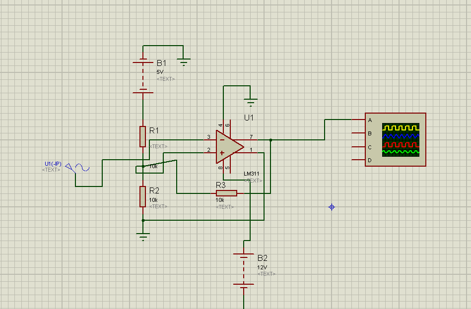
I need help in designing a schmitt trigger schematic using the LM311 opamp. I want to convert 110V-AC pure sine wave into a square wave so I can then feed this to a MCU and measure the period of the 110V-AC. What I have in mind so far is to step down the 110 to about 12V-AC but I am not sure of how to connect the LM311. Also, I am using a voltage divider with 2 10k resistors and +5V so at the non-inverting I should have 2.5V and the signal would be fed into the inverting side but I was wondering if the 12V-AC has to be lower?
Please help!!!
- - - Updated - - -
Here is the schematic in Proteus however I get an error message and its not simulating. The message says no model specified for U1 and simulation failed due to partition analysis error. Where did I go wrong

Hello Members,
I need help in designing a schmitt trigger schematic using the LM311 opamp. I want to convert 110V-AC pure sine wave into a square wave so I can then feed this to a MCU and measure the period of the 110V-AC. What I have in mind so far is to step down the 110 to about 12V-AC but I am not sure of how to connect the LM311. Also, I am using a voltage divider with 2 10k resistors and +5V so at the non-inverting I should have 2.5V and the signal would be fed into the inverting side but I was wondering if the 12V-AC has to be lower?
Please help!!!
- - - Updated - - -
Here is the schematic in Proteus however I get an error message and its not simulating. The message says no model specified for U1 and simulation failed due to partition analysis error. Where did I go wrong
Last edited: