Continue to Site

Welcome to EDAboard.com

Welcome to our site! EDAboard.com is an international Electronics Discussion Forum focused on EDA software, circuits, schematics, books, theory, papers, asic, pld, 8051, DSP, Network, RF, Analog Design, PCB, Service Manuals... and a whole lot more! To participate you need to register. Registration is free. Click here to register now.

Problem of voltage on PIN AN0 in PIC Controller

Status
Not open for further replies.

ecaits

Member level 4
Joined
Jan 16, 2014
Messages
76
Helped
0
Reputation
0
Reaction score
0
Trophy points
6
Activity points
579
Dear All Friends,

I am working on PIC16F877 for ADC.

I am giving analog input 0-5V to pin AN0 by 0-5 volt pots.

Suppose, I am giving 2.5 V by pots on AN0. Now I am measuring the voltage at pin AN0 so I am getting apporx. 2.5V. But when I run the program by MPLAB, at that time I am getting approx 4.97 V at pin AN0.

Why this happen??? I cannot understand.

Plz help me.
 

Although the PIC AN0 input draws only leakage current, it does draw some current when the voltage is sampled. To get a one bit accuracy on the PIC (4.8mV at 5V) the A-D the source impedance should be less than 10K. Is your pot less than 10K?
 

Yes it is 5K.
 

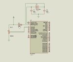
I think nikhilt007 meant YOUR circuit diagram :-o

The (almost) 5V is coming from somewhere and if the pot is wired correctly it only leaves the PIC itself. My guess, without seeing the program or schematic is that you have the pin configured in digital mode instead of analog and it is working as a digital output instead of analog input.

Brian.
 

Hi,

Your circuit should look like the picture below.

The power on default for pin RA0 is Analogue Input so unless you have changed anything in your software it should work ok.

You should be able to measure 2.5v at pin RA0 with a voltmeter.

Post your circuit and program code if you are still having problems.
 

Attachments

  • 000093.jpg
    000093.jpg
    35 KB · Views: 72

But I cannot understand the pin RA0 circuit diagram, attached in file.

I can measure the same 2.5 V on pin RA0 when program is on halt, but when I run the program at that time it shows approx 4.73V on pin RA0 pin. Why it happen so???

Plz help me to solve it.
 

Attachments

  • RA0.pdf
    8.3 KB · Views: 62

Which is what I suggested in post #6.

ecaits, please tell us what value you are writing to the ADCON1 register.

Explanation: the RA0 pin can work in three modes, a digital input, a digital output or an analog input. Obviously, to measure an analog voltage you want it to be in analog input mode. If it is set to digital input you would read back '0' from the pin until the pot was about half way around then it would suddenly change to '1'. In digital output mode it will try to drive the pin high or low from inside the PIC. From your description, you have it in digital output mode and are driving the pin to 4.73V from inside the PIC itself.

Brian.
 

Status
Not open for further replies.

Part and Inventory Search

Welcome to EDABoard.com

Sponsor

Back
Top