Continue to Site

Welcome to EDAboard.com

Welcome to our site! EDAboard.com is an international Electronics Discussion Forum focused on EDA software, circuits, schematics, books, theory, papers, asic, pld, 8051, DSP, Network, RF, Analog Design, PCB, Service Manuals... and a whole lot more! To participate you need to register. Registration is free. Click here to register now.

help,a 4-way power divider without the isolation resistor

Status
Not open for further replies.

Tomsin yin

Banned
Joined
Mar 6, 2014
Messages
61
Helped
5
Reputation
10
Reaction score
5
Trophy points
8
Activity points
0
hi,all
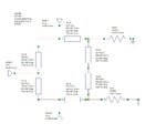
now im working on a 4-way power divider without the isolation resistor R,but when simulation it,unfortuately,i get bad results.
my question is:
1.the VSWR(S44) and VSWR(S55) of the output side is more than 4.0,i don't know why it is so big.
2.is the impendence of the quarter-wave 70.71ohm?
the files as follow: ZBEW6SSMZDZIS~Z[PIHXVE5.jpgI`0A{A%~NWBF7E6Z6BH}]EC.jpg

- - - Updated - - -

thnx in advance!
 

Attachments

  • power divider.zip
    50.4 KB · Views: 86

Not easy to tell from the image. It does not show all of the device.

The difficulties of bringing the tracks together to be able to fit a resistor across, as in the classic Wilkinson splitter is solved by using the variant known as "Gysel" splitter.

Read all about it here
Gysel **broken link removed**

The advantages are many compared to the simple junction split with quarter-wave matching sections.
 

Attachments

  • Gysel_Splitter.jpg
    Gysel_Splitter.jpg
    47.7 KB · Views: 86

hi,Darktrax
thnx for ur help,but i can use "Gysel" splitter on request.first i design a two-way splitter without isolution resistor,the picture shows my design that one subcircuit and another is the same, the parameters as following:H=1.6mm,Er=4.4,Mur=1,Cond=4.1E+7,Hu=1.0e+033mm,T=0.05mm,TanD=0.0003 and Rough=0mm.i think my matching is correct,but VSWR(S22) is nearly 3.0,i can't understand,so can you help me? thnx in anvance.YI1FAU(0B5OPVE~2506FFLQ.jpg
 

it is still hard to see what is going in that picture. Is TL2 a quarter wave transformer, and everything else is 50 ohm line? If so, make sure the length of TL2 is quarterwave at midband. Also, the impedance of the TL2 should be Ztl2=√(50*100) = 70.7 ohms (assuming you want a 2:1 splitter). That puts two 100 ohm load impedances in parallel at the Tjunction
 

Status
Not open for further replies.

Part and Inventory Search

Welcome to EDABoard.com

Sponsor

Back
Top