markbng
Junior Member level 1
Hi,
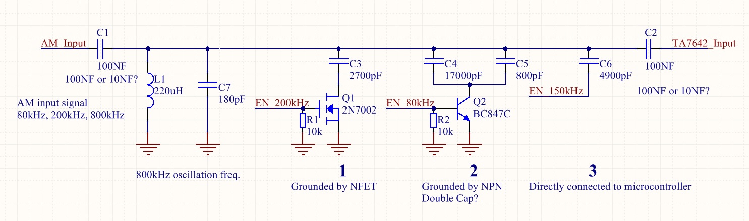
Thanks for reading my message. I want to make an AM demodulator that demodulates up to 4 fixed frequencies. The AM demodulation frequencies are 83kHz, 200kHz, 455kHz and 800kHz. Please take a look at my schematic. The AM signal is passed through C1. Please tell me what input capacitor is better (10NF or 100NF? 100NF has more inductance? or it doesn't matter if only the capacitor material is NP0/C0G?). I want to control the fixed selectable frequency by selecting the right capacitor in the circuit by enabling the IO for option 1, 2 or 3. Which option is better? The NFET that connects the capacitor to the ground or a transistor? I also saw a schematic that connects the capacitor directly to the microcontroller IO (IO in high Z or ground). I don't think this option is optimal (since I don't know the characteristics of the output stage of the microcontroller and longer connections to the microcontroller). So what option is the best solution? How about the output capacitance of the NFET and/or transistor. Is Coss (Output Capacitance) of the NFET always present or only when switched off? What is the capacitance of non conducting NFET and transistors? what about conducting NFETs and transistors?
What about the 2 capacitors in parallel at option 2? Is that a problem? What capacitors must I use for this reception filter circuit? Thanks in advance for your help")
Kind regards,
Mark
Thanks for reading my message. I want to make an AM demodulator that demodulates up to 4 fixed frequencies. The AM demodulation frequencies are 83kHz, 200kHz, 455kHz and 800kHz. Please take a look at my schematic. The AM signal is passed through C1. Please tell me what input capacitor is better (10NF or 100NF? 100NF has more inductance? or it doesn't matter if only the capacitor material is NP0/C0G?). I want to control the fixed selectable frequency by selecting the right capacitor in the circuit by enabling the IO for option 1, 2 or 3. Which option is better? The NFET that connects the capacitor to the ground or a transistor? I also saw a schematic that connects the capacitor directly to the microcontroller IO (IO in high Z or ground). I don't think this option is optimal (since I don't know the characteristics of the output stage of the microcontroller and longer connections to the microcontroller). So what option is the best solution? How about the output capacitance of the NFET and/or transistor. Is Coss (Output Capacitance) of the NFET always present or only when switched off? What is the capacitance of non conducting NFET and transistors? what about conducting NFETs and transistors?
What about the 2 capacitors in parallel at option 2? Is that a problem? What capacitors must I use for this reception filter circuit? Thanks in advance for your help
Kind regards,
Mark