Continue to Site

Welcome to EDAboard.com

Welcome to our site! EDAboard.com is an international Electronics Discussion Forum focused on EDA software, circuits, schematics, books, theory, papers, asic, pld, 8051, DSP, Network, RF, Analog Design, PCB, Service Manuals... and a whole lot more! To participate you need to register. Registration is free. Click here to register now.

[SOLVED] How Can I generate clock pulses for 50Hz square wave inverter using TMR2 and PR2

Status
Not open for further replies.

Mithun_K_Das

Advanced Member level 3
Joined
Apr 24, 2010
Messages
899
Helped
24
Reputation
48
Reaction score
26
Trophy points
1,318
Location
Dhaka, Bangladesh, Bangladesh
Activity points
8,252
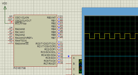
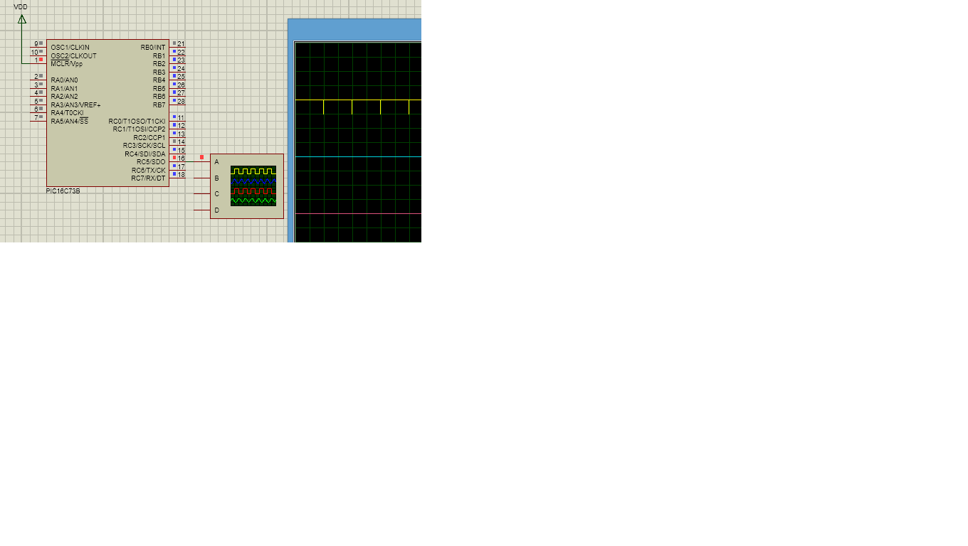
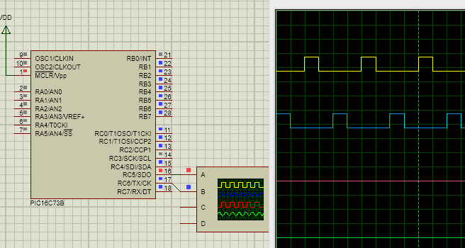
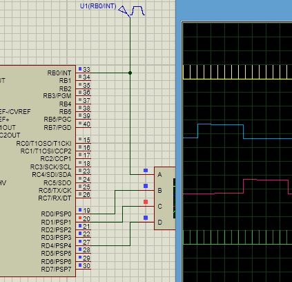
How Can I generate clock pulses for 50Hz square wave inverter using TMR2 and PR2?

That means I want to make a PWM signal using timer2 module. And need to generate 2 push-pull type signals for this purpose.


Can you give me an example code in microC?
 

You can just have the TMR2 running; use the Timer 2 interrupt. Use a flag to decide which output to drive. In the ISR, use that flag info to drive the required output and update the flag to reflect that in the next ISR, the other output should be driven. That, I would think, should be a quite reliable method.
 

I was trying this:

Code C - [expand]
1
2
3
4
5
6
7
8
9
10
11
12
13
14
15
16
17
18
19
20
21
22
23
24
25
26
27
28
29
30
31
32
33
34
35
36
37
38
39
40
41
42
43
44
45
46
47
48
49
50
51
52
53
void interrupt()
{
  if(TMR2IF_bit)
  {
     TMR2IF_bit = 0;
     Clock1 = ~Clock1;
  }
}
 
void PORT_Ini(void)
{
   TRISA = 0xFF; // PORTA input
   TRISB = 0b00000001; // PORTB output except RB0 & RB1
   PORTB = 0x00; // all zero
   TRISC = 0b00001000; // PORTC output
   PORTC = 0x00; // all zero
}
 
 
void main()
{
   PORT_Ini(void);
   
   Lcd_Init();
   Lcd_Cmd(_LCD_CLEAR);
   Lcd_Cmd(_LCD_CURSOR_OFF);
 
   
   Buzzer = 1;
   Delay_ms(500);
   Buzzer = 0;
   Delay_ms(500);
   
   ADCON1=0x00;
   
   OPTION_REG = 0x00;
   // Timer settings
   T2CON = 0b01011101;
   CCP2CON = 0b00001010;
   TMR2 = 0;
   PR2 = 255;
   GIE_bit = 1;
   PEIE_bit = 1;
   //TMR2IE_bit = 1;
   while(1)
   {
       Run_IPS(void);
       Get_Battery(void);
       Display_Battery(void);
       LCD_Parameter(0);
 
   }  // while
}// void main


But its not working.... :(

Whats the problem?
 

What is the crystal frequency? Make outputs digital using adcon1 register.
For 4Mz crystal set prescaler to1/4, postscaler to 1/10 and 249 value for PR2. You will get interrupt at 100Hz. Assign a flag and toggle it on each interrupt. Alternately set and reset phase of push-pull outputs.
 

X-Tal is 10MHz, Also I need to vary the duty cycle of the push-pull signal pair within this 50Hz.
Can I use compare module in this case?
 

This is for PIC16F


Code C - [expand]
1
2
3
4
5
6
7
8
9
10
11
12
13
14
15
16
17
18
19
20
21
22
23
24
25
26
27
28
sbit PORT2TOGGLE at RC0_bit;
 
//Timer2
//Prescaler 1:16; Postscaler 1:7; TMR2 Preload = 223; Actual Interrupt Time : 9.9932 ms
 
//Place/Copy this part in declaration section
void InitTimer2(){
  T2CON = 0x36;
  PR2 = 223;
  TMR2IE_bit = 1;
  INTCON = 0xC0;
}
 
void Interrupt(){
  if (TMR2IF_bit){
         PORT2TOGGLE = ~PORT2TOGGLE;
         PR2 = 223;
         TMR2IF_bit = 0;
 
  }
}
 
void main() {
 
 
     InitTimer2();
 
}


:D you've just put the code from timer calculator...

No bro, it not that one. I need to make a push-pull pulse. That means there will be two signals with anti-phase with each other.

Also need to vary the duty cycle of each pulse without changing the frequency... Hopefully I've done that section already using Timer2 and little bit Timer0.

Thanks.
 

[video]http://filmy.elektroda.net/27_1393179976.flv[/video]
When there is slight difference in voltage on ADC pin, correction is slow. With big difference adjustment is fast. It tries to maintain ADC input within 125-130 value. Frequency remains at 50Hz.
 
Give more detail about the project, such as schematic, what is to be displayed on the LCD and what are the inputs and outputs, and how microcontroller should process them.
 

That will be a very very long description. It is an inverter circuit with charging control. I need to generate the 50Hz PWM signal with PIC16F73 and need to show some data in the LCD(16X2). Also when the mains is available, the MCU will control the charging section (TRIAC Based) too. The whole process is controlled by only this MCU.

Also UPS mode will be working all the time. **broken link removed**
 

See this one:

View attachment circuit.bmp

Can you give me an example code of compare module? How can I use this module to generate a square wave pulse?


I was trying with this:


Code C - [expand]
1
2
3
4
5
6
7
8
9
10
11
12
13
14
15
16
17
18
19
20
21
22
23
24
25
26
27
28
29
30
31
32
33
34
35
36
37
38
39
40
41
42
43
44
45
46
47
48
49
50
51
52
53
#define   Clock1   RC5_bit
void interrupt()
{
    if(CCP1IF_bit)
    {
       CCP1IF_bit = 0;// clear flag
       Clock1 = 0;
 
    }
    if(TMR2IF_bit)
    {
      Clock1 = 1;
      TMR2IF_bit = 0;//clear flag
    }
 
} // ISR...
 
void PORT_Init(void)
{
   TRISA = 0xFF; // PORTA input
   TRISB = 0b00000001; // PORTB output except RB0 & RB1
   PORTB = 0x00; // all zero
   TRISC = 0b00001000; // PORTC output
   PORTC = 0x00; // all zero
}
 
 
void main()
{
   PORT_Init(void);
 
   // Timer2 settings for 7ms interrupt
   T2CON = 0x36;
   PR2 = 223; // 10 ms time
   TMR2IE_bit = 1;
   INTCON = 0xC0;
   
   // compare module settings...
   CCP1CON = 0b00001011;// trigger special event
   CCP1IE_bit = 1;
   CCPR1L = 0x1B;
   CCPR1H = 0xCF;
   //timer 1 settings...
   T1CON = 0x01;
   TMR1IF_bit = 0;
   TMR1H = 0xCF;//10ms timer
   TMR1L = 0x2B;
 
   while(1)
   {
 
   }  // while
}// void main


Output is: View attachment 102500
Can you tell me what the wrong I'm doing here?
 

The number of instruction cycles in 10ms at 10MHz is equal to 25000. It should not exceed that. It turns out to be,
Code:
  CCPR1H = 0x61;
   CCPR1L = 0xA8;
You may want duty cycle to be between 50%-99%.
For example,
Code:
  CCPR1H = 0x31;
   CCPR1L = 0xA8;
Here are the two different duty cycles.


You have to clear timer1 on timer2 interrupt. See the code.
Code:
#define   Clock1   RC5_bit
void interrupt()
{
    if(CCP1IF_bit)
    {
       CCP1IF_bit = 0;// clear flag
       Clock1 = 0;

    }
    if(TMR2IF_bit)
    {
      Clock1 = 1;
      TMR2IF_bit = 0;//clear flag
      TMR1H = 0x00;//Clear  timer1
      TMR1L = 0x00;
    }

} // ISR...

void PORT_Init(void)
{
   TRISA = 0xFF; // PORTA input
   TRISB = 0b00000001; // PORTB output except RB0 & RB1
   PORTB = 0x00; // all zero
   TRISC = 0b00001000; // PORTC output
   PORTC = 0x00; // all zero
}


void main()
{
   PORT_Init(void);

   // Timer2 settings for 7ms interrupt
   T2CON = 0x36;
   PR2 = 223; // 10 ms time
   TMR2IE_bit = 1;
   INTCON = 0xC0;

   // compare module settings...
   CCP1CON = 0b00001011;// trigger special event
   CCP1IE_bit = 1;
   CCPR1L = 0xA8;
   CCPR1H = 0x31;
   //timer 1 settings...
   T1CON = 0x01;
   TMR1IF_bit = 0;

   while(1)
   {

There may be is a difference between 16C73B and 16F73 in memory organisation. Compile it with 16C73B to simulate in Proteus.
 
Code:
#define   Clock1   RC5_bit
#define   Clock2   RC6_bit
unsigned short flag=0;
void interrupt()
{
    if(CCP1IF_bit)
    {
       CCP1IF_bit = 0;// clear flag
       Clock1 = 0;
       Clock2 = 0;
    }
    if(TMR2IF_bit)
    {
      TMR2IF_bit = 0;//clear flag
      TMR1H = 0x00;//Clear  timer1
      TMR1L = 0x00;

      if(flag)
      {
      Clock1 = 1;
      flag=~flag;
      }
     else
      {
      Clock2 = 1;
      flag=~flag;
      }
    }

} // ISR...

void PORT_Init(void)
{
   TRISA = 0xFF; // PORTA input
   TRISB = 0b00000001; // PORTB output except RB0 & RB1
   PORTB = 0x00; // all zero
   TRISC = 0b00001000; // PORTC output
   PORTC = 0x00; // all zero
}


void main()
{
   PORT_Init(void);

   // Timer2 settings for 7ms interrupt
   T2CON = 0x36;
   PR2 = 223; // 10 ms time
   TMR2IE_bit = 1;
   INTCON = 0xC0;

   // compare module settings...
   CCP1CON = 0b00001011;// trigger special event
   CCP1IE_bit = 1;
   CCPR1L = 0xA8;
   CCPR1H = 0x31;
   //timer 1 settings...
   T1CON = 0x01;
   TMR1IF_bit = 0;

   while(1)
   {

   }  // while

   }

 
Yes, I've done this section for Push-pull. But another problem occured, when I'm using LCD display to show any message... it makes noise and LCD shows garbage. What is the solution in this case?

Here what I did in modification...

Code C - [expand]
1
2
3
4
5
6
7
8
9
10
11
12
13
14
15
16
17
18
19
20
21
22
23
24
25
26
27
28
29
30
31
32
33
34
if(CCP1IF_bit)
            {
                 CCP1IF_bit = 0;// clear flag
                 Clock1 = 0;
                 Clock2 = 0;
                 LCD_Lock  = 1;
            }
            if(TMR2IF_bit)
            {
                if(oscillation)
                {
                    if(!clock_cycle)
                     {
                         Clock1 = 1;
                         Clock2 = 0;
                     }
                     if(clock_cycle)
                     {
                         Clock1 = 0;
                         Clock2 = 1;
                     }
                     clock_cycle = ~clock_cycle;
                 }
                 else
                 {
                      Clock1 = 0;
                      Clock2 = 0;
                 }
                 LCD_Lock  = 0;
                // for timer mechanism....
                TMR2IF_bit = 0;//clear flag
                TMR1H = 0x00;//Clear  timer1
                TMR1L = 0x00;
            }


oscillation is used to enable/disable oscillation
and LCD_Lock is used in LCD program further...
 
Last edited:

Is there any condition that if Compare module works hardware interrupt pin INT will not work?

What I found in interfacing LCD with that Push-pull program for my Inverter it doesn't take INT as interrupt. That is why the LCD is not showing right characters. Also INT is not working. But if I cut the compare section, it works.

- - - Updated - - -

INT Doesn't work.png

INT is not working according to the signal at pin INT. It works only with Compare module interrupt.

- - - Updated - - -

And the circuit Diagram is: ckt.png
 

What is making trouble is the LCD program. I tried and make a solution of this. Here what I did:

This my ISR program

Code C - [expand]
1
2
3
4
5
6
7
8
9
10
11
12
13
14
15
16
17
18
19
20
21
22
23
24
25
26
27
28
29
30
31
32
33
34
35
36
37
38
39
40
41
42
43
44
45
46
47
void interrupt()
{
 
            if(CCP1IF_bit)
            {
                 CCP1IF_bit = 0;// clear flag
                 Clock1 = 0;
                 Clock2 = 0;
                 LCD_Lock  = 1;
            }
            if(TMR2IF_bit)
            {
                if(oscillation)
                {
                    if(!clock_cycle)
                     {
                         Clock1 = 1;
                         Clock2 = 0;
                     }
                     if(clock_cycle)
                     {
                         Clock1 = 0;
                         Clock2 = 1;
                     }
                     clock_cycle = ~clock_cycle;
                 }
                 else
                 {
                      Clock1 = 0;
                      Clock2 = 0;
                 }
                 LCD_Lock  = 0;
                // for timer mechanism....
                TMR2IF_bit = 0;//clear flag
                TMR1H = 0x00;//Clear  timer1
                TMR1L = 0x00;
            }
             
             /*if(INTF_bit && !oscillation)
            {
               Charging_Clk = ~Charging_Clk;
               LCD_Lock = 0;
               INTF_bit = 0;
            }*/
 
 
} // ISR...


Here I used LCD_Lock as a variable and it is used in the LCD section. What I'm doing here is, when there is a time gap, LCD_Lock will be cleared. And the LCD section will wait until its being clear by calling a Function:


Code C - [expand]
1
2
3
4
5
void Trick_Delay(void)
{
      while(LCD_Lock==0);
      Delay_ms(2);
}


And this Trick_Delay is used in just before LCD program:


Code C - [expand]
1
2
3
4
5
6
7
8
9
10
11
12
13
14
15
16
17
18
19
20
21
22
23
24
25
26
27
28
29
30
31
32
33
34
35
36
37
38
39
40
void LCD_Parameter(short LCD_message)
 {
 
     if(LCD_message==0)
     {
        Trick_Delay(void);
        Lcd_Out(1,1,"ALL_OFF ");
     }
     if(LCD_message==1)
     {
         Trick_Delay(void);
         Lcd_Out(1,1,"IPS_RUN ");
     }
     if(LCD_message==2)
     {
        Trick_Delay(void);
        Lcd_Out(1,1,"MAINS_ON");
     }
     if(LCD_message==3)
     {
        Trick_Delay(void);
        Lcd_Out(1,1,"CHARGING");
     }
     if(LCD_message==4)
     {
        Trick_Delay(void);
        Lcd_Out(1,1,"CH_FULL ");
     }
     if(LCD_message==5)
     {
        Trick_Delay(void);
        Lcd_Out(1,1,"LOW_BATT");
     }
     if(LCD_message==6)
     {
        Trick_Delay(void);
        Lcd_Out(1,1,"OVERLOAD");
     }
     Delay_ms(50);
 }


This is how I solved the LCD problem. But another problem is now happening... If I enables the INT interrupt [Hardware interrupt] All system stops and INT is not working as it should work. Its not responding rather than just creating a CCP1 interrupt and Timer2 interrupt.
Also LCD becoming mad. So now what the modification I can do here?

Any help?
 

I experimented with RB0-int and compare module. Int causes a 10uS pulse on RD4. It never misses a pulse.
3956639700_1393745732.jpg
 

Status
Not open for further replies.

Part and Inventory Search

Welcome to EDABoard.com

Sponsor

Back
Top