Jepoy
Newbie level 2
Hi everyone,
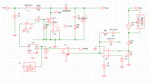
I've been trying to implement a compensated closed-loop current mode(CM) controlled boost converter using the SIMPLIS engine. However, I am having convergence issues with the simulator.
Here are the converter specs I followed: Vi = 12V, Vo=18V, Io=1A, fs=100khz.
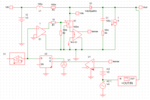
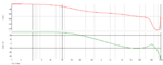
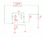
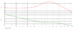
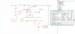
To have a solid understanding of CM, I used primitive components available in SIMPLIS such as discrete comparators, controlled sources, an S-R latch and a parameterised op amp. I started off my attempt to close the loop by generating a control-to-output bode plot using SIMPLIS's AC analysis. From these plots, I designed a type II compensator.
I wanted a crossover frequency of fc=fs/10=10khz and a phase margin of 45 degrees. From the bode plots, the converter had a gain of -10dB and a phase of about -120 degrees at f=fc. This meant the compensator needed to give a gain of 10dB and phase boost of 45-(-120+90)=75 degrees. Using the k-factor method of determining the R's and C's of the compensator, I came up with the standard op-amp based implementation. I confirmed my design by generating the transfer function of my compensator in SIMetrix software. The op amp used in this design was the standard LM358.
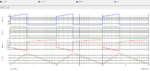
Now what's left to do was to close the loop - connect the compensator to the converter. However, SIMPLIS POP analysis is unable to converge. I tried to set initial conditions on the inductor and capacitors, but the analysis still won't converge. I have been stuck with this problem for the past week :-( still no progress.
Could anyone point mo to the right direction? What am I doing wrong? Is my understanding of CM, based on the circuits, flawed? Are there other factors I failed to account for? Any help would be appreciated :grin:
Here are the simulations files for reference:
**broken link removed**
**broken link removed**
**broken link removed**
I've been trying to implement a compensated closed-loop current mode(CM) controlled boost converter using the SIMPLIS engine. However, I am having convergence issues with the simulator.
Here are the converter specs I followed: Vi = 12V, Vo=18V, Io=1A, fs=100khz.
To have a solid understanding of CM, I used primitive components available in SIMPLIS such as discrete comparators, controlled sources, an S-R latch and a parameterised op amp. I started off my attempt to close the loop by generating a control-to-output bode plot using SIMPLIS's AC analysis. From these plots, I designed a type II compensator.
I wanted a crossover frequency of fc=fs/10=10khz and a phase margin of 45 degrees. From the bode plots, the converter had a gain of -10dB and a phase of about -120 degrees at f=fc. This meant the compensator needed to give a gain of 10dB and phase boost of 45-(-120+90)=75 degrees. Using the k-factor method of determining the R's and C's of the compensator, I came up with the standard op-amp based implementation. I confirmed my design by generating the transfer function of my compensator in SIMetrix software. The op amp used in this design was the standard LM358.
Now what's left to do was to close the loop - connect the compensator to the converter. However, SIMPLIS POP analysis is unable to converge. I tried to set initial conditions on the inductor and capacitors, but the analysis still won't converge. I have been stuck with this problem for the past week :-( still no progress.
Could anyone point mo to the right direction? What am I doing wrong? Is my understanding of CM, based on the circuits, flawed? Are there other factors I failed to account for? Any help would be appreciated :grin:
Here are the simulations files for reference:
**broken link removed**
**broken link removed**
**broken link removed**