Continue to Site

Welcome to EDAboard.com

Welcome to our site! EDAboard.com is an international Electronics Discussion Forum focused on EDA software, circuits, schematics, books, theory, papers, asic, pld, 8051, DSP, Network, RF, Analog Design, PCB, Service Manuals... and a whole lot more! To participate you need to register. Registration is free. Click here to register now.

Microtek UPS output voltage high

Status
Not open for further replies.

lrahirwar

Newbie level 3
Joined
Jan 26, 2014
Messages
4
Helped
0
Reputation
0
Reaction score
0
Trophy points
1
Activity points
59
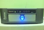
I have at my home a Microtek Inverter / UPS 875 VA E2. Today, when mains was cut, I checked output voltage of the UPS and it was 300 volts without load and 280 volts with moderate load (not full load). Altough, I am using this inverter for more than 1 year and have no other problem, yet the output voltage must be 220 v (plus minus 5%). Can any learned friend from this forum suggest how I myself correct output voltage around 220 volts?
 

From the detail you provided it seems that the kit used inside the UPS doesn't have voltage regulation / fix volt option. This type of kits (low cost) works the way you describe. The output voltage is intentionally set high and is reduced as you put load on it.
If you want to have a stabilized voltage then the only option is to change the Kit inside the UPS with kit that have fix volt option.
 

an you also observe that the intensity of an incandescent bulb also changes when this voltage change? Often multimeters show wrong readings because the output is not pure sine wave. A bulb can show the power by its illumination.
 

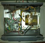
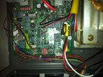
Thanks! iukhan for giving your valuable advice in connection with high output voltage of my UPS. How can I be confirmed that the kit used is cheap type? I am herewith attaching images of the UPS. Please see these images and suggest further accordingly. UPS1.JPGUPS2.JPGUPS3.JPG

- - - Updated - - -

Thanks! ALERTLINKS, for providing your valuable suggetion in connection with high output voltage of my Microtek UPS. I observed when power cut, intensity of an incandescent bulb increases. I uploaded 3 images of the UPS. Whats your further opinion regarding the matter?
 

From the pictures you attached, I have the following conclusions
a) This UPS doesn't have low cost KIT.
b) There are two POTs (Variable resistors) for adjustment but regarding their purpose the picture is unclear.
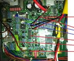
c) I may be able to comments further if you can provide the ICs Number (Mark Red) and POTs label (Mark Blue in the picture attached here).
UPS3.JPG
 
photo.JPGUPS5.jpgUPS6.jpgUPS7.JPGUPS4.jpg
From the pictures you attached, I have the following conclusions
a) This UPS doesn't have low cost KIT.
b) There are two POTs (Variable resistors) for adjustment but regarding their purpose the picture is unclear.
c) I may be able to comments further if you can provide the ICs Number (Mark Red) and POTs label (Mark Blue in the picture attached here).
View attachment 101600

Thanks iukhan again for your kind interest to help me.
I am here with sending the required information.
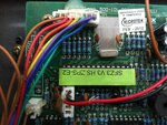
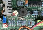
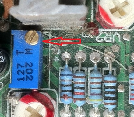
1. There are two POTs (variable resistors) marked blue, their clear picture is being given below, their values not visible on POTs.
2. First two red marked ICs are 4N35L15, third red marked IC is LM324N, fourth red marked IC has a sticker on it which is marked SFZ3 V3 HS ZPS-E2, fifth red marked IC is LM555CN.
 
Last edited:

There is an other pot present which is rectangular blue colour, ten turn pot. I guess this is for adjusting output. First note its position and then turn two turns clockwise and observe output. Try also in anticlockwise direction. If nothing happens, reset it to its original position. You can also try with the other two pots.

2376257900_1391089287.jpg
 

1. There are two POTs (variable resistors) marked blue, their clear picture is being given below, their values not visible on POTs.
2. First two red marked ICs are 4N35L15, third red marked IC is LM324N, fourth red marked IC has a sticker on it which is marked SFZ3 V3 HS ZPS-E2, fifth red marked IC is LM555CN.

from the data you provided, now I have the follow comments
1. This kit have two optocoupler, one op amp, one 28 pin microcontroller, one LM555 IC and three POTs.
2. Most probably this is a sinewave KIT.
3. Since the Kit uses two optocoupler 4N35 and generally one opto is used for Input AC sense and other opto is used for feedback/output voltage sense. This means that this kit should give fix output voltage.
4 . The POTs are labeled as VR1, VR2 etc and have no label for its functionality. Moreover, two POTs seems to be unchanged (Factory default setting). The third one is multiturn. You can give a try to this POT but remember to reset it to its original position as suggested by ALERTLINKS. BUT as far as my experience tell that generally multiturn POT in UPS Kit is used for overload setting. So consider little hope from this POT setting.
5. So what I conclude is that there is a faulty component in the feedback loop which may be one of the optocoupler 4N35 or output voltage rectifying diodes.
 

2. Most probably this is a sinewave KIT.
As i know Microtek UPS is famous brand.
Circuit is consist with push pull type square wave inverter.
And most sine wave inverters are in H-BRIDGE configuration with 7 to 20 khz switching frequency.
Regarding 4N35 one is for mains sense and second is being used for zero cross detection.
I think this inverter do not have output volt control.
 

Status
Not open for further replies.

Similar threads

Part and Inventory Search

Welcome to EDABoard.com

Sponsor

Back
Top