Continue to Site

Welcome to EDAboard.com

Welcome to our site! EDAboard.com is an international Electronics Discussion Forum focused on EDA software, circuits, schematics, books, theory, papers, asic, pld, 8051, DSP, Network, RF, Analog Design, PCB, Service Manuals... and a whole lot more! To participate you need to register. Registration is free. Click here to register now.

Class-E power oscillator / inverter for ultrasonic needed

Status
Not open for further replies.

neazoi

Advanced Member level 6
Joined
Jan 5, 2008
Messages
4,123
Helped
13
Reputation
26
Reaction score
15
Trophy points
1,318
Location
Greece
Activity points
36,955
High I need a sinusoidal ef power generator circuit operating in class-E (for high efficiency) in the range of 35-100KHz 5-30W or so.
just a power oscillator, not a generator followed by an audio amplifier.
Any propositions?
 

I doubt if it's a reasonable approach.

If you want high efficiency, you'll start the design from the output stage, which in turn defines the required control signal. In some cases you might be able to make the output stage self oscillating without loosing much efficiency, more likely you don't achieve this. So you have the choice self-oscillating or high efficiency.

Other design parameters are probably more interesting like supply voltage and output impedance.
 

Unless you have already experience in power oscillator design where the load may resonate also, I would not go for this approach.

Oscillators with resonating loads can/will behave in a very strange manner. The acoustic load may very likely change and this changes the electrical load. This may detune the oscillator to a new optimum working point (maintaining good efficiency), but may also detune the oscillator to a frequency where output power drops significantly and/or efficiency drops significantly. Such a design isn't easy.

If you can be sure the electrical load (impedance as seen by the oscillator) is free of high Q resonances around the operating frequency, it can be done, but still it is a serious design task.
 

Thanks a lot,
So the best approach for high efficiency would be an ultrasonic oscillator followed by a class-D amplifier?
 

Thanks a lot,
So the best approach for high efficiency would be an ultrasonic oscillator followed by a class-D amplifier?
I would not say it is the best approach, but it is an easier approach (from a technical standpoint of view).

Instead of class D, other highly effcient topologies can be used. If your load varies with time, you may need a feedback system to make sure the final stage keeps operating at high efficiency. At least you need some measurement to shut down the circuit to avoid damage (similar to VSWR protection in RF amplifiers).
 

I would not say it is the best approach, but it is an easier approach (from a technical standpoint of view).

Instead of class D, other highly effcient topologies can be used.

You refer to class-E? I have not seen a class-E ultrasonic amplifier design ever. The lowest ones I have seen are to 137KHz.
 

You can use whatever topology you like / you have experience with. If you have experience with class-D, just try it, as this is an easy to build topology at your power level, and you may only need to sweep frequency to find a good operating point. Do you have any idea of the impedance of the transducer as you need this to design the matching/filter circuit that is between the half (or full) bridge stage and the load?

Regarding other topologies: In the recent past high power ultrasonic converters (kW range) were built with extremely fast switching thyristors. LC resonance was used to turn-off the thyristor. For some years ago I wanted to use thyristors in a high power half bridge application, but very fast thyristors are obsolete, or at least hard-to-get. It became a resonant converter with fast IGBTs and SIC rectifiers.

If you can use supply voltage < 100V, I would go for a mosfet output stage because of ease of drive, good switching speed and low Rdson.
 

You refer to class-E? I have not seen a class-E ultrasonic amplifier design ever.
So you doubt it's feasibility or practicality? But you listed class E as a requirement in the thread title and post 1.:-?

You still haven't mentioned other design requirements such as load impedance or supply voltage.

Do you want the frequency to be continuously adjustable, or at least easy to change, or would you be happy to replace a few inductors and capacitors every time you wanted to change the frequency?

Do you want the output power to be adjustable, or are you happy with a fixed output power anywhere in the range you mentioned?
 

You can use whatever topology you like / you have experience with. If you have experience with class-D, just try it, as this is an easy to build topology at your power level, and you may only need to sweep frequency to find a good operating point. Do you have any idea of the impedance of the transducer as you need this to design the matching/filter circuit that is between the half (or full) bridge stage and the load?

Regarding other topologies: In the recent past high power ultrasonic converters (kW range) were built with extremely fast switching thyristors. LC resonance was used to turn-off the thyristor. For some years ago I wanted to use thyristors in a high power half bridge application, but very fast thyristors are obsolete, or at least hard-to-get. It became a resonant converter with fast IGBTs and SIC rectifiers.

If you can use supply voltage < 100V, I would go for a mosfet output stage because of ease of drive, good switching speed and low Rdson.

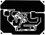
My intention is to use it on an audio magnetic amplifier, so a clean sinewave is desirable. It will be connected to a transformer winding, not to a transducer of any kind. The only easy to build solution up to 10w I have found is the class-D TDA7480. In the datasheet the PCB layout is shown. With a little bit of image editing the PCB copper layer can be extracted.
I hope it can go up to 35-40KHz or so.
I have not found any simpler to build circuit, although I seek a more powerfull one.
 

Attachments

  • Untitled2.png
    Untitled2.png
    29.7 KB · Views: 93

Preferably the sine waveform (if required my the magnetic amplifier?) will be generated by a filter. This reduces the output stage to a simple switcher generating a square wave.
 

At such low frequencies, a voltage mode class D (basically a half bridge or full bridge) will give best efficiency over a wide frequency range. However efficiency will depend on your load impedance, and you still haven't really told us anything about your load...
 

Status
Not open for further replies.

Part and Inventory Search

Welcome to EDABoard.com

Sponsor

Back
Top