shaikss
Full Member level 4
Hi,
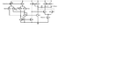
I am working on the design of Instrumentation amplifier for ECG system. Initially, I designed a Difference differential amplifier. When I checked the Gain and Phase margin response, the system is highly unstable.
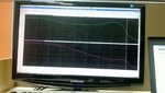
I observed phase margin in negative value and 3dB cut off frequency at ten's of MHz.
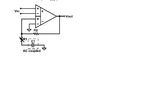
I tried to add a resistor in series with cap but there is no change in Phase margin.
I did pole-zero analysis:
Poles:
1. -3.22+02 Hz
2. -5.417+07 hz
3. -2.513+07 Hz
4. -9.684e+07 Hz
5. -3.19e+08 Hz
6. -5.27+e08 Hz
Zeros
1. -2.7941e+06 Hz
2. -4.922e+07 Hz
3. -9.679 e+07 Hz
4. -3.14e+08 Hz
5. 6.94232e+07 Hz
6. 2.43 e+09 Hz
7. 9.01661 e+09 Hz
Can you pls tell me how to improve the Phase margin?
I am working on the design of Instrumentation amplifier for ECG system. Initially, I designed a Difference differential amplifier. When I checked the Gain and Phase margin response, the system is highly unstable.
I observed phase margin in negative value and 3dB cut off frequency at ten's of MHz.
I tried to add a resistor in series with cap but there is no change in Phase margin.
I did pole-zero analysis:
Poles:
1. -3.22+02 Hz
2. -5.417+07 hz
3. -2.513+07 Hz
4. -9.684e+07 Hz
5. -3.19e+08 Hz
6. -5.27+e08 Hz
Zeros
1. -2.7941e+06 Hz
2. -4.922e+07 Hz
3. -9.679 e+07 Hz
4. -3.14e+08 Hz
5. 6.94232e+07 Hz
6. 2.43 e+09 Hz
7. 9.01661 e+09 Hz
Can you pls tell me how to improve the Phase margin?