Continue to Site

Welcome to EDAboard.com

Welcome to our site! EDAboard.com is an international Electronics Discussion Forum focused on EDA software, circuits, schematics, books, theory, papers, asic, pld, 8051, DSP, Network, RF, Analog Design, PCB, Service Manuals... and a whole lot more! To participate you need to register. Registration is free. Click here to register now.

Using Bi-Colour Led to show state of fuse.

Status
Not open for further replies.

kkeeley

Member level 3
Joined
Jul 29, 2009
Messages
59
Helped
1
Reputation
2
Reaction score
1
Trophy points
1,288
Location
Australia
Activity points
2,877
Hi,

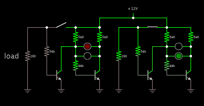
I am wishing to place a small circuit on each of my power rails between my power supply and test circuits so that I can tell when a voltage rail goes over current. I have found a circuit that I think will work nicely for the positive voltage rails, but I'm not 100% sure how to make it work for the negative voltages. Below is an example of the positive voltage circuit, the switch would be replaced by a re-settable fuse and the load would be placed between S1/R1 and ground.


Fuse Led.png

Can I reverse/change the transistors for the negative voltages or will I also need to reconfigure the bias resistors as well. If so what would be the best way to reconfigure the circuit?

Thanks in advance,
Kenneth
 

For the fun of it, I made a simulation of your circuit.

Switch off... one led glows.

Switch on... other led glows.

Screenshot with two identical circuits side by side (switch positions are different):


Changing the supply voltage only makes the led's change in brightness.
 
Thanks for the reply, I was fairly certain that the circuit would work for a positive voltage rail, my question is how to make the idea work for a negative voltage.

ps. what program did you simulate the circuit in? I like the way the current paths appear to be highlighted when active, and the leads changed colour.
 

You may consider a simpler solution without transistors.
 

Attachments

  • LED_ind.gif
    LED_ind.gif
    9 KB · Views: 107
Thank you E-design for your circuit, this circuit should be perfect, it handles both the positive and negative voltages and will allow me to use either two leg or three leg bi-colour leds. All I need to do is adjust the resistor values to suit the different voltages.

Kenneth
 

ps. what program did you simulate the circuit in? I like the way the current paths appear to be highlighted when active, and the leads changed colour.

The simulator is Falstad's interactive animated simulator. Free to download and use at www.falstad.com/circuit.

I had it create a weblink containing my entire schematic. It will open the falstad website, load my schematic into his simulator, and run it on your computer.

https://tinyurl.com/khtnuwd

The wires turn green to show positive, red to show negative.

Yellow dots travel down the wires, at a speed proportional to amperage.
 
Status
Not open for further replies.

Similar threads

Part and Inventory Search

Welcome to EDABoard.com

Sponsor

Back
Top