Continue to Site

Welcome to EDAboard.com

Welcome to our site! EDAboard.com is an international Electronics Discussion Forum focused on EDA software, circuits, schematics, books, theory, papers, asic, pld, 8051, DSP, Network, RF, Analog Design, PCB, Service Manuals... and a whole lot more! To participate you need to register. Registration is free. Click here to register now.

Impedance mismatches

Status
Not open for further replies.

jf1020

Newbie level 5
Joined
Nov 13, 2013
Messages
9
Helped
0
Reputation
0
Reaction score
0
Trophy points
1
Activity points
56
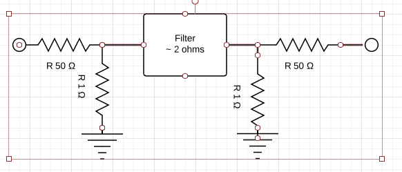
How can you translate a P1dB for a 1 ohm circuit that is mismatched from the 50 ohm test equipment

There is a resistive impedance match, but of course that doesnt work well over the frequency range that us 500 MHz to 1 G

The circuit looks like this right now:


What should be the meaning of P1db for a passive filter?
 

The problem is that 1 ohm real impedance can't be easily implemented for wide band, I wonder how the interface of your filter looks like?

But provided you made an impedance matching network, you can verify it's parameters with a network analyzer.

The other point is that the divider has > 30 dB attenuation, so you'll need a lot of input power to achieve reasonable power levels at the 1 ohm interface.
 

Status
Not open for further replies.

Similar threads

Part and Inventory Search

Welcome to EDABoard.com

Sponsor

Back
Top