Continue to Site

Welcome to EDAboard.com

Welcome to our site! EDAboard.com is an international Electronics Discussion Forum focused on EDA software, circuits, schematics, books, theory, papers, asic, pld, 8051, DSP, Network, RF, Analog Design, PCB, Service Manuals... and a whole lot more! To participate you need to register. Registration is free. Click here to register now.

[PIC] Interfacing 230Vac into PIC

Status
Not open for further replies.

leorickings

Junior Member level 1
Joined
Oct 18, 2013
Messages
17
Helped
0
Reputation
0
Reaction score
0
Trophy points
1
Activity points
197
Hi, I'm new in the forum so please point out if I make mistake...

I am designing a gas detector system with PIC16F877A.

Most sensors work on 5Vdc which has no problem interfacing with the PIC.

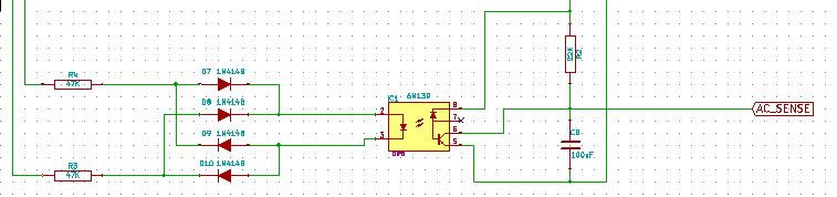
However the gas detector runs on the mains has a rating of 230Vac,
therefore when gas is detected, its signal output is 230Vac. How do I input this signal into the PIC?
I considered using relays, but is there any relay with 230Vac coil and 5Vdc contact?
There is also optocoupler, is there any optoisolator matching my needs?

I do appreciate all inputs, please share your ideas and experience with me :D
Thanks thanks
 

i consider following output
when no gas leak= 0VAC & when gas leak detect = 230 VAC (+/-10%)

Now use resistor network such that u get low AC output so use resistor network such 660K [220K *3] & 4.7K All are 1/4 W. This give around 1.62 Vrms apply this output to half bridge rectifier & check DC voltage. No if u require isolation then use PC817 as opto coupler. Output of Opto coupler can connect to controller
 
You can get relays with 230V coils, the contact rating is unimportant because the load you are switching is so tiny. The best solution is an opto-coupler though, they are smaller, cheaper and more reliable. Use something like a 6N139, feed it from a bridge rectifier (4 x 1N4148 will do) and feed each AC arm of the bridge through 47K resistors from the 230V AC. The opto output with a pull-up resistor will pulse at twice line frequency, if you need it to be a steady logic level output, add a capacitor across it to even out the pulses.

Brian.
 
Thanks for the inputs, I will try both of your suggestions, btw yes I am intend to detect the existence of 230VAC as "gas detected" and vice versa. However, if I am using voltage divider (the resister in series method), wouldn't the resistors be very hot if the 230Vac flows through it for a long time?

Brian, if I want steady voltage level into my pic instead of pulses, how do I determine which capacitor value to use?

Thanks :D
 

I would strongly advise you do not use the resistor dividing method because it requires a direct connection to the incoming AC supply and hence can provide a lethal electric shock. If you use the opto-coupler method it will give complete isolation from the power lines and therefore should be safe.

The optimal capacitor value depends on the value of pull-up resistor you use and the AC power frequency but in your application the value does not have to be precisely calculated. If you use a 10K pull-up resistor and a 1uF capacitor it should work fine. The idea is the capcitor charges to VDD through the resistor and stays there unless the opto-coupler turns on and discharges it. So if you ground the opto emiter pin and connect the collector to the pull up resistor and then to VDD, with the capacitor across the collector and emitter, it will give logic '1' when AC is not present and '0' when it is. If you need it the other way around, connect the opto collector to VDD and the resistor as a pull-down to ground in it's emitter.

Brian.
 

Thanks, I will give it a try.

I recently came across a transformerless design where 230vac is stepped down to low voltages with capacitors and resistors.
There 230vac is connected to (1M Ohm resistor and 400V 334J capacitor in parallel), then series with a 1K Ohm resistor, then into a bridge rectifier, lastly into a 22uF 50V capacitor (polar, radial electrolytic) in parallel.
The capacitor is in blue coatnig, polyester film (the square thing), the 1M Ohm resistor has 5 bands, which i guess is a non-flammable type, and the 1K Ohm resistor is a 5W.

I suppose the voltage this circuit produces is very low, since the final load are the NE555 and LEDs and a buzzer.
Couldn't verify it though since it is a spoiled buzzing pilot lamp.

Is this a good solution? The components are simpler to obtain and lesser, with less connections too. How do I implement capacitors and resistors to get 5V from 230vac?
Is there any specific rating for the components i need to use?

Please do help, thanks.

- - - Updated - - -

You can get relays with 230V coils, the contact rating is unimportant because the load you are switching is so tiny. The best solution is an opto-coupler though, they are smaller, cheaper and more reliable. Use something like a 6N139, feed it from a bridge rectifier (4 x 1N4148 will do) and feed each AC arm of the bridge through 47K resistors from the 230V AC. The opto output with a pull-up resistor will pulse at twice line frequency, if you need it to be a steady logic level output, add a capacitor across it to even out the pulses.

Brian.

Hi Brian,

My optocoupler has just arrived, it was the SFH620A with AC input photodiodes. I connected 1K Ohm resistors to each arm of AC input, and connected leds with resistors between the +5Vcc and the Collector of the optocoupler. When I switched on the 230Vac power, for a brief second it worked. The LED at the output side lights up, but after a split second (like, 1second) the 1K Ohm resistors connected to the AC arms burst into flame! It actually caught fire!

The optocoupler is not damaged though. What had i done wrong in the connection? Shoulid I use higher resistance? or should i use resistors with higher power rating?
 

If interfacing a diode bridge to AC - be sure to pick diodes with voltage ratings approx 2X the AC voltage that will be applied to them.
It would seem that you didn't properly size your resistors if they burst into flames. Understand what "working voltage" and "maximum voltage" are for a resistor, and be sure to keep your resistors chosen to avoid violating those parameters. Also, Power through the resistor will be V*V/R, so if you had 2K resistors with 230V across them -> 26.45W of peak power -- so if your resistors weren't 15W or more each, yes, they will get hot and burn up. Be CAREFUL! CHOOSE HIGHER RESISTANCE AND POWER RATING so that your current is within specs for the optocoupler and that you are no more than 70% of rated power for the resistors chosen as a starting point (even then, they will get quite warm).

Geez, no wonder my resistors are charred as coal...

I have another problem, the resistors available to me now are the usual 1/4W type, connecting one in each 230Vac arm they can sustain 1/2W, the resistance I will need is
V²/R = 1/2
R = 105.8kOhm (literally)

However the current flowing through would be only 230/105.8k = 2.1mA
is there any optocoupler input operating at such low current? The SFH620A datasheet only states its max current, have no idea on the min
 

Before going any further - do you fully understand the safety issues of using a capacitive voltage dropper?

Although they are cheaper and smaller than transformers, they give no isolation from the incoming power whatsoever. If there is ANY chance that you or anyone else can touch any components or wiring, including switches or the shaft of any variable component, DO NOT USE THIS METHOD. The only time it is aceptable to use a capacitive dropper is when the entire circuit is enclosed and water-tight, even then, special capacitors are used and the circuit has to be fused.

Please explain in more detail exactly what you are trying to achieve. Are you powering the whole circuit from the dropper circuit or only using it to sense whether AC is present or not? If you are only using it to sense AC, what are you using to power the remainder of the circuit?

The SFH620A isn't the best choice in AC sensor applications, it does need quite a high LED current. Something like a 6N139 and external bridge rectifier will operate down to about 0.5mA. I use then for sensing 230V AC with 2 x 47K resistors in series and 4 x 1N4148 as a bridge rectifier. The resistors are only 0.25W rated and run cold.

Brian.

Brian,

Yes I do realize that the circuit related to the mains requires isolation and that is why I prefer optoisolators.

I am building a control unit to be mounted in a junction panel for gas detection system. However the signal from the industrial gas detector sensor gives a signal of 230Vac. While 16F877A can only sense 5Vdc I must do something to the 230Vac. The remainder of the circuit is powered from another power supply, so only the 5Vdc side of the opto will have common ground with them. The 230Vac signal is isolated.

I chose the SFH620A because the input side are two LEDs anti parallel, which makes it compatible with AC. But if the 6N139 runs at very low current then I will give it a try.
You mentioned using 1N4148 diodes as bridge, wouldn't that make your opto output pulsate at double the 230Vac frequency?

My system only detects the signal once, and triggers all the required alarm, and stop taking signals until it is reset. So even if it pulsates I wouldn't be worried, since the alarm triggers when the opto activates at the rectified signal first peak. But if the 230Vac 50KHz signal runs continuously, the 6N139 will keep getting rectified signals at 100KHz, same goes to the output side of the opto, switching on and off at 100KHz frequency. Will this damage the opto?
 

It's Hz not KHz - you are thinking 1,000 times too fast :-D

Opto isolators are very reliable and have very long life expectancy, even when run at high speed. I have been using 6N139 and similar devices at 6MHz in one application for more than 10 years without any problems.
Yes, the output will pulse at twice the line frequency, you could put a 1N4148 across the opto LED input to clamp the voltage and then it would produce a pulse per half cycle. the reason I use a bridge is for the small extra cost of three diodes, it halves the time constant needed at the output to turn it into a 'clean' logic level when a capacitor is connected across it's output. The RC time constant of the pull-up resistor and shunt capacitor make it easy to produce a logic level output instead of pulses.

Brian.

Ops sorry, had to think 1000 times faster to meet the dateline :-o

Does that mean, it's ok even if I don't add a capacitor after the rectifier? Let the rectified signal pulsates, the first 5V pulse triggers the alarm, and it sounds the alarm until the system is being reset, I wouldn't need to create a steady logic level right?
 

That's right.

How the software reacts to pulses is all that matters. If you need a steady logic level, it's easier and safer to add the capacitor after the opto-coupler rather than before it. With the SFH620 you have no option but to do it that way because the input (LED) side is AC anyway. The idea is that from the processors point of view, it's input pin sees a pull-up resistor to VDD and a capacitor down to ground. The capacitor charges up and the PIC sees a logic '1' on it's pin. When the opto conducts, it provides a path for the capacitor to discharge and the voltage across it drops making the PIC see a logic '0'. By making the time constant of the pull-up resistor/capacitor relatively long compared to the AC period, the presence of power is converted to a steady logic level.

This is an extract of a circuit I used recently. The 230V input is on the left and the output went to a 16F88 processor.


Brian.


Thanks for the sharing, appreciate it :D
About the resistors at both the DC arms, i will have 230*230/(47000*2)W of power to be dissipated, which is 0.56W. So is using the normal 1/4W resistors fine? Secondly, how do I decide the suitable value for the capacitor?
 

That will be peak power, not average, so you will be OK - the average power for the sine wave will be ((Vp/sqrt(2)) **2)/R, so the RMS Voltage will be approx 162V, and average power is thus 0.282 Watts for the 94K ohms you have, divided across the (2) 0.25W resistors will give you acceptable voltage margin, provided that you are using typical 1/4 Watt through hole parts)
 
Thanks Ftsolutions, you beat me to it!

For the pull-up resistor and capacitor, I used 22K and 100nF, these will give a reasonably fast response and are easily available. The values are not critical, if you make the resistor smaller it will simply waste current, if you make it much bigger there is a risk of not reaching logic high level. With the capacitor, a higher value will slow the response time and a lower value will cause ripple on the logic high voltage.

Incidentally, I used 2 x 47K in the AC side rather than a single 94K (100K) resistor to reduce the voltage across each resistor, some small resistors are only rated to 250V or less before risk of internal arcing. I put one in each arm of the AC for safety on the PCB, electrically they could be in series in one arm. I figured if a short occurred, and this particular unit would be usd in a damp environment, I would rather have a 47K resistor in series with the incoming mains power than nothing at all.

Brian.
 

leo thanks for your question it really brought a lot of knoledge out.

betwixt: thanks for your time in expaining all those.

pls I have questions:

1 . can I use pc817 opto as well.
2. in implementng a feedback loop for inverter voltage regulation can your schematic work? will the output of the opto vary with the imput voltage?

thanks.
 

1. Yes, but the PC817 needs at least 2mA to switch properly and ideally wants 5mA or more so the input resistors would have to be smaller values and higher power rated.

2. No, as shown, the circuit will only detect the presence of AC, it cannot tell what voltage it is. The PC817 can (and usually is) used for regulation feedback but it requires that the LED curent is proportional to the voltage you are regulating. The best source of information on PC817 usage is on-line schematics of ATX power supplies where is is commonly used to isolate the DC output side of the SMPS from the switching side.

Brian.
 

Have you seen transformerless powersupply circuits? Try using it to get 12V AC from 230V AC and then convert it to DC and drop it to 5V using voltage divider for ADC input.
 

Thanks for the suggestions, I think there is PC817 around my area, since it might be the only thing available, I must have a go on it. However in the datasheet it is stated that the absolute maximum rating for forward current is 50mA, how do I know the minimum current needed to switch on the opto?

Tried SFH620A, switching on currnt is too high, the resistors charred, 6N139 is not available in my place... Cracking my head
 

Status
Not open for further replies.

Similar threads

Part and Inventory Search

Welcome to EDABoard.com

Sponsor

Back
Top