Continue to Site

Welcome to EDAboard.com

Welcome to our site! EDAboard.com is an international Electronics Discussion Forum focused on EDA software, circuits, schematics, books, theory, papers, asic, pld, 8051, DSP, Network, RF, Analog Design, PCB, Service Manuals... and a whole lot more! To participate you need to register. Registration is free. Click here to register now.

Forcing an audio signal through a transformer, best way?

Status
Not open for further replies.

neazoi

Advanced Member level 6
Joined
Jan 5, 2008
Messages
4,122
Helped
13
Reputation
26
Reaction score
15
Trophy points
1,318
Location
Greece
Activity points
36,951
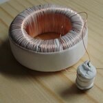
Hello, I have a toroidal core biased to a point using a big number of turns.
I need to find the best way to induce an audio signal to the core.

An initial thought was to use a capacitor connected to the audio source and the one end of the DC coil, to block DC back to the audio source and to pass the signal through the DC coil. But the DC coil has many turns and this presents some resistance to the low level audio signal.
Another thought was to wind a separate winding onto the core and insert the audio signal there. This coils will have lower number of turns thus it will not present a significant loss to the signal source, whereas the core will be biased from the separate DC coil.

I would like your comments on these, or any other suitable way.
 

You have not explained what you are trying to do. If you are passing DC through one winding (to establish a certain flux level?), then how ever you try and introduce an AC signal it will be loaded by the impedance of the DC source. So for this sort of thing to work, you need your DC source to have a high impedance, or better still modulate it with your AC.
Frank
Hi Frank,
I am trying to make a magnetic audio amplifier similar to this http://sparkbangbuzz.com/mag-audio-amp/mag-audio-amp.htm but in another output configuration. I am trying 600T for the primary in my version hoping to make it getting to the linear section of the BH curve more easily (my cores are bigger anyway). I am using square loop toroids hoping to get more amplification with less input signal, but the biasing will be more tricky.
600T on the control winding present 20R dc resistance so I am thinking the separate winding for the signal.
The sparknbuzz guy is doing it using a capacitor.
"how ever you try and introduce an AC signal it will be loaded by the impedance of the DC source". Is there any way to overcome this?
 

In the sketch the DC is applied via a 220 ohm resistor (1k would be better), this is what stops the AC being shorted out. You will have to wind a centre tapped secondary. Toroids are a devil to wind. Work out what length of wire you will need for one half of the secondary (perimeter of toroid +20% X number of turns). Make a shuttle that will pass through the centre of the toroid. Get twice the length of wire, fold it in half, wrap it around the shuttle, pass the shuttle through the toroid and off you go (winding both halves at the same time)!! :)
Frank
 
  • Like
Reactions: neazoi

    neazoi

    Points: 2
    Helpful Answer Positive Rating
In the sketch the DC is applied via a 220 ohm resistor (1k would be better), this is what stops the AC being shorted out. You will have to wind a centre tapped secondary. Toroids are a devil to wind. Work out what length of wire you will need for one half of the secondary (perimeter of toroid +20% X number of turns). Make a shuttle that will pass through the centre of the toroid. Get twice the length of wire, fold it in half, wrap it around the shuttle, pass the shuttle through the toroid and off you go (winding both halves at the same time)!! :)
Frank

I have figured out how to wind the turns no problem, I have already wound 600T and continuing, within a few hours. When a layer of turns occupies the core, I use plumpers PTFE tape to secure the layer and insulate it from the next layer. Then the next layer is wound and so on. (covering with PRFE is not needed, because no HV there, I just thought it to be a good solution to keep the layers from overlapping, plus the result is more mechanically stable.
Anyway, when you say I need a center tapped secondary, you mean for the signal input or the load output winding?
 

And don't expect good results!

What it is doing is using the primary winding as a controlled inductance, using the audio and DC combined to saturate the core. The high frequency exciter voltage is then 'strangled' before being rectified and fed to the loudspeaker. A similar technique is used in power line voltage regulators and in the 'old days' of color TV, to provide raster shape correction in a 'transductor'. It is a very inefficient amplifier and tends to be extremely non-linear so expect high distortion. With all those inductors and capacitors in the path, expect some strange frequency responses too!

You will probably get better results using a pot core rather than ferrite rings. Note that you can get the same result with one primary for the audio and one for the DC, this eliminates the coupling capacitor but the load impedance will still vary with the DC current.

Brian.
 
  • Like
Reactions: neazoi

    neazoi

    Points: 2
    Helpful Answer Positive Rating
And don't expect good results!

You will probably get better results using a pot core rather than ferrite rings. Note that you can get the same result with one primary for the audio and one for the DC, this eliminates the coupling capacitor but the load impedance will still vary with the DC current.
Brian.

All right, anyway I think I will try this, as impedance is not so much of a problem in audio like in RF. Oh, I do not expect more than 10KHz to come out, but it may depend on the core properties, who knows.
The cores I am using are square loop toroids and theoretically they should achieve high gain, provided that they are correctly biased to operate into their linear region only. Why they are inefficient? General cores are, but why square loop ones are too?

Any guess about the number of turns for the "audio input" winding, or where to start from, 10T, 50T, 100T? The control wiring has more than 600T. Core up to now attached.
 

Attachments

  • core1.jpg
    core1.jpg
    28.1 KB · Views: 53

If you look at your diagram, the secondary is 25+25 turns. The secondaries should be balanced so the flux that results from the 35 KHZ is equal in both halves so it cancels out, no magnetic flux equals no leakage inductance, hence more 35 KHZ current for a given voltage.
Frank
 

I didn't mean to imply the cores are inefficient, I meant the amplifier as a whole. Any power at the loudspeaker has to start as 35KHz AC and preferably as a sine wave so much of the power consumed by the circuit as a whole will be taken by the power amplifier producing the 35KHz itself. It's more like a controlled attenuator than an amplifier.

I'm not sure the shape of the core and windings will play much part in it's performance. I'm no expert in magnetics but I would have thought the reason for 'squarer' rather than round section toroids was simply to allow more space in the center hole for wires to pass through.

If I remember correctly, the transductors I used years ago were ferrite 'E' shaped cores back to back (three legs facing the other three legs) with the control winding only around the middle leg. I think there was something unusual about the core though, I may be wrong but I think the outside legs were in contact but the middle ones were very slightly shorter with a paper shim between them.

Incidentally, the original schematic uses 1N4003 diodes which are not really suitable at 35KHz, you would dramatically improve the output by using fast switching diodes or Schottky types.

Brian.
 

I'm not sure the shape of the core and windings will play much part in it's performance. I'm no expert in magnetics but I would have thought the reason for 'squarer' rather than round section toroids was simply to allow more space in the center hole for wires to pass through.
Brian.[/QUOTE]

No I do not mean their physical size when I refer to square loop, but their properties. Their BH curve linear section is very steep compared to ordinary toroids and this turns out to a high ration of output to input signal, hence more gain.

Yes I have red about these three legged cores, and they are wound as you refer.

The 35KHz generator consumes the whole power of the amplifier, the core is only used as a regulator. Book literature states that at least a 1:5 frequency should be used for better results so I expect better a 100KHz oscillator to be used for 20KHz audio. Since frequency stability is not so much of a problem, and since 100KHz is in the just below LW, an efficienr class-E amplifier could be used to bring this signal to appropriate levels.
 

Status
Not open for further replies.

Part and Inventory Search

Welcome to EDABoard.com

Sponsor

Back
Top