Continue to Site

Welcome to EDAboard.com

Welcome to our site! EDAboard.com is an international Electronics Discussion Forum focused on EDA software, circuits, schematics, books, theory, papers, asic, pld, 8051, DSP, Network, RF, Analog Design, PCB, Service Manuals... and a whole lot more! To participate you need to register. Registration is free. Click here to register now.

Overload protection circuit in tl494 and sg3524 inverter

Status
Not open for further replies.

hamid159

Full Member level 3
Joined
Aug 25, 2013
Messages
176
Helped
14
Reputation
28
Reaction score
14
Trophy points
1,298
Location
Lahore
Activity points
2,488
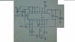
I have made an inverter using tl494 and sg3524 chips but there is no overload protection circuit.what changes should I make for the protection circuit.
 

Pin 10 of SG3524 is shutdown pin. You need to sense your load either from the sources of your fets or from the output of the inverter. logical 1 on pin 10 will shutdown the inverter and protect your output.
 
i have a circuit in which pin 10 is grounded by a resistor of 10k...what should i do?inverters output is modified sine wave...so can it be used for sensing??
 

In my view post your circuit diagram here so one can suggest you on this....it's very hard to imagine from only the post.....

with regards,

milind
 

Here's the circuit diagram
 

Attachments

  • phpd2RuHwAM.jpg
    phpd2RuHwAM.jpg
    82.1 KB · Views: 547

you should do as Fidelis indicated:

"Pin 10 of SG3524 is shutdown pin. You need to sense your load either from the sources of your fets or from the output of the inverter. logical 1 on pin 10 will shutdown the inverter and protect your output."

The secret is how to sense the current....you could use either a low valued resistor or a hall-cell based sensor. See the Allegro's semiconductor website for suitable devices.
I suggest using the hall sensor since it provides isolation.
The output of the hall sensor may be fed to a comparator circuit, which will pull pin 10 "high" whenever the current is exceeded.
 
Last edited:

Thanks schmitt trigger,,,,,,i'm using full bridge mosfet at the output..so source of which mosfet i have to join with pin 10 through small resistor???

- - - Updated - - -

can i connect pin 10 with reference voltage pin by a resistor????????
 

I believe I know what your circuit looks like, but without a full circuit diagram, I cannot provide an accurate suggestion.
 

that's the circuit...both files contain the complete circuit....
 

Attachments

  • tl494.bmp
    88.9 KB · Views: 337
  • sg3524.bmp
    88.9 KB · Views: 259

A possible resistor location.

You must use a comparator like a LM393 to trip at voltages above 1 volt (with hysteresis). The comparator output will then drive pin 10 high. I chose V= 1 volt arbitrarily, you may use a value which will provide a standard resistor value.
Calculate the resistor value R =V/Imax and its power P =R*Imax^2

This is an absolutely basic circuit. Many further refinements are possible.
 

Attachments

  • possible resistor location.bmp
    54.1 KB · Views: 300

Status
Not open for further replies.

Part and Inventory Search

Welcome to EDABoard.com

Sponsor

Back
Top