Continue to Site

Welcome to EDAboard.com

Welcome to our site! EDAboard.com is an international Electronics Discussion Forum focused on EDA software, circuits, schematics, books, theory, papers, asic, pld, 8051, DSP, Network, RF, Analog Design, PCB, Service Manuals... and a whole lot more! To participate you need to register. Registration is free. Click here to register now.

How to realize a parallel RC circuit given the real and imaginary part of impedence

Status
Not open for further replies.

shaikss

Full Member level 4
Joined
Jun 18, 2007
Messages
229
Helped
1
Reputation
2
Reaction score
1
Trophy points
1,298
Activity points
3,319
Hi,

I need to realize the parallel combination of RC Network.
I have the details of Real and imaginary part of impedance of rectifier circuit. Now, I need to realize the rectifier circuit in terms of parallel combination of RC network.
How should I do?
On top of it, I have to do matching network for the same.
Pls guide me how to proceed.

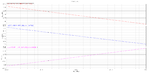
I have attached the plot of 'Y' which I got when I simulated the impedance of rectifier circuit.
 

Attachments

  • imp_1.02.png
    imp_1.02.png
    25.7 KB · Views: 122
  • circuit.png
    circuit.png
    75.2 KB · Views: 129

Just a couple of questions:

1. I suppose the "Y" is the admittance of your circuit. Is it correct ?
2. do you have to model the impedance in a single point (a see the marker placed at 953 MHz) or for the whole span 950 - 960 MHz ?
 

Are you sure that you want RC instead of less lossy and noisy LC?
Are you sure that it not is the conjugate matching network you want?
Y seems more like Z?
If you can attach a s1p-file for rectifier impedance and frequency range is it easy to solve.
 

The Z of parelell RC:

tau=RC (your chosen frequency. This time constant of circuit.)

omega=1/tau

s=j*omega

Z=1/(sC) ---> The result is a complex number. ;)

The realized paralell RC must have same real, imaginary and phase with your rectifier. (for P(max))

For define the phase:
 

Attachments

  • paralell RC niquist.bmp
    611.3 KB · Views: 100
Last edited:

Are you sure that you want RC instead of less lossy and noisy LC?
Are you sure that it not is the conjugate matching network you want?
Y seems more like Z?
Yes, of course, it's a Z diagram (equivalent circuit is a RC series circuit). And it's almost purely capacitive, the real part can be most likely ignored in a technical sense.

But the impedance curve doesn't represent the shown transistor circuit because it's the result of an AC (small signal) simulation without the rectifier in operation.
https://www.edaboard.com/threads/299568/
 

Status
Not open for further replies.

Part and Inventory Search

Welcome to EDABoard.com

Sponsor

Back
Top