Continue to Site

Welcome to EDAboard.com

Welcome to our site! EDAboard.com is an international Electronics Discussion Forum focused on EDA software, circuits, schematics, books, theory, papers, asic, pld, 8051, DSP, Network, RF, Analog Design, PCB, Service Manuals... and a whole lot more! To participate you need to register. Registration is free. Click here to register now.

How do we design a Microcontroller Based Battery Charger ?

Status
Not open for further replies.

muhibraza

Member level 1
Joined
Oct 11, 2010
Messages
38
Helped
3
Reputation
6
Reaction score
3
Trophy points
1,288
Activity points
1,578
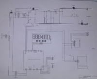
hello I need to implement the following circuit for charging a 24V battery. Can someone guide me how do I write the algorithm for driving the SCRs through PWM ? And I also need to know which parameters are to be considered while charging the battery. And also the best method to calculate the firing angle for triggering the SCRs.


Firing angle of the SCR can be controlled using Interrupt pin of the microcontroller .... you can generate using Timers ....
 

Firing angle of the SCR can be controlled using Interrupt pin of the microcontroller .... you can generate using Timers ....

brother how do we find out what value of the fully rectified waveform would be considered to charge the battery ? the average value or the rms ? and how do we find out the firing angle for achieving that value ?
 

brother how do we find out what value of the fully rectified waveform would be considered to charge the battery ? the average value or the rms ? and how do we find out the firing angle for achieving that value ?

https://www.edaboard.com/threads/112533/

you might find this link useful..
Moreover u can get Vdc value from Vrms.now once you find correct value of Vdc u can fire the triac accordingly....
you can even get an idea from the mobile phone chargers ... there the current and the voltage values are mentioned ...
 

I know how to find the Vdc and Vrms for a certain signal and in my case, the full wave rectified pulsating dc signal. I know its rms value (Vrms = 0.707 Vp) and its average value too (i.e. Vdc = 2Vp / 3.142)
But I am confused about which one will dictate the charging voltage to be given to the battery ? In other words, I want to ask is it the Average Value (Vdc) of the waveform that charges the battery or is the the RMS Value (Vrms) that charges it ? If I simplify more, I would ask that if I need to charge the battery to 13.2 volts through a fully rectified pulsating signal, should I set its RMS value to 13.2 volts or should I set the Average value to 13.2 volts ?

It's actually the Vdc value that is of major concern. you must find Vdc for finding the correct value,then you can compare it with Vrms of the waveform.This will help you in deciding at what value of waveform is sutaible for your battery charging...
 

Status
Not open for further replies.

Similar threads

Part and Inventory Search

Welcome to EDABoard.com

Sponsor

Back
Top