Continue to Site

Welcome to EDAboard.com

Welcome to our site! EDAboard.com is an international Electronics Discussion Forum focused on EDA software, circuits, schematics, books, theory, papers, asic, pld, 8051, DSP, Network, RF, Analog Design, PCB, Service Manuals... and a whole lot more! To participate you need to register. Registration is free. Click here to register now.

What is the natural time constant of a DC-DC converter

Status
Not open for further replies.

bhl777

Full Member level 6
Joined
Sep 30, 2008
Messages
363
Helped
0
Reputation
0
Reaction score
0
Trophy points
1,296
Activity points
5,140
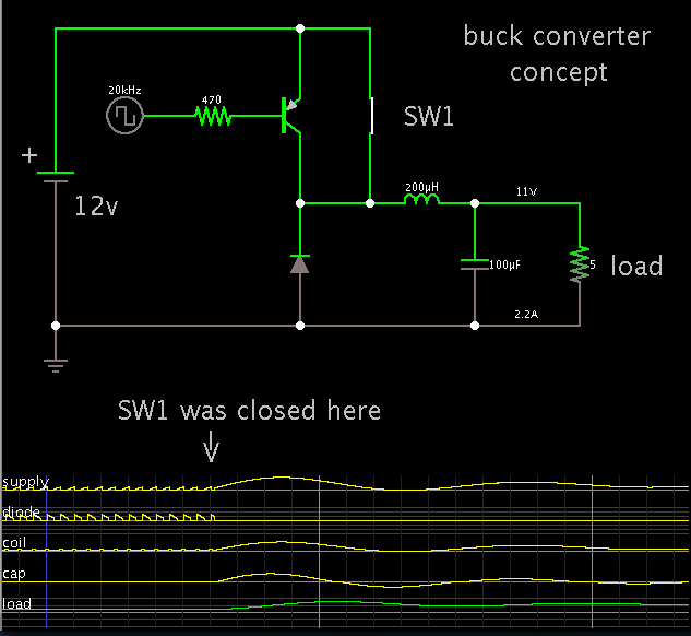
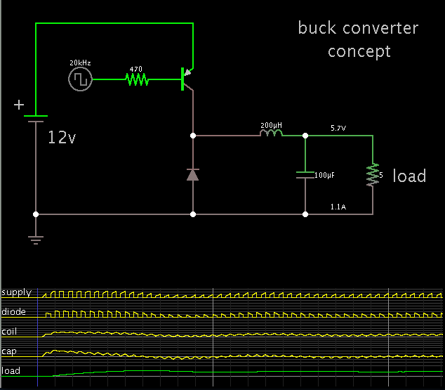
When we analyze the switching regulator, textbooks only mentioned that the switching frequency is much higher than time constant of converter itself. But nowhere mentioned what exactly this time constant is. Could anybody advise what is this?
For example, we have a buck circuit with fsw=400kHz, how can we explain the switching frequency is much faster than natural time constant?
Thanks!
 

The time constant comes from the coil and capacitor values.

Unstable operation results if the switching frequency is close to the resonant frequency.

Here is a simulation to portray the effect of the resonant frequency.


The scope traces begin by showing several cycles of normal running.

Then a switch was closed to bypass the transistor. This creates a resonant LC tank circuit. The waveform is much longer than the switching waveform.

The LC tank frequency is suppressed while the converter is running normally.

However when power is first applied, the sudden shock induces LC resonance for a few cycles.

 
  • Like
Reactions: bhl777

    bhl777

    Points: 2
    Helpful Answer Positive Rating
Hi BradtheRad, thank you for your help! I have another question, since in synchrounous buck, LC resonant frequency is the same order as switching frequency, (for example, F_lc=50kHz, F_sw=400kHz), we need some compensator to make it stable. But under this circumstances, can we still treat PWM converter as a sampler?


The time constant comes from the coil and capacitor values.

Unstable operation results if the switching frequency is close to the resonant frequency.

Here is a simulation to portray the effect of the resonant frequency.


The scope traces begin by showing several cycles of normal running.

Then a switch was closed to bypass the transistor. This creates a resonant LC tank circuit. The waveform is much longer than the switching waveform.

The LC tank frequency is suppressed while the converter is running normally.

However when power is first applied, the sudden shock induces LC resonance for a few cycles.


Hi BradtheRad, thank you for your help! I have another question, since in synchrounous buck, LC resonant frequency is the same order as switching frequency, (for example, F_lc=50kHz, F_sw=400kHz), we need some compensator to make it stable.

This is a ratio of 1 to 8. It should work okay.

However if your point addresses what happens when the ratio is an exact integer, then there may be a chance it will induce a certain amount of resonant action.

But under this circumstances, can we still treat PWM converter as a sampler?

You specify synchronous mode... which has a switch at both the high and low side (rather than having a diode in one position).

When you mention sampling, I suppose that in a manner of speaking, the converter (a) first samples the supply V, then it (b) samples ground 0V?

And the coil carries ramp waves up and down, as determined by the L/R time constant. Thus the output is an intermediate level, based on the duty cycle.

I have not heard of the sampling concept associated with this action. I don't know what else to say about it.
 

Status
Not open for further replies.

Part and Inventory Search

Welcome to EDABoard.com

Sponsor

Back
Top