Continue to Site

Welcome to EDAboard.com

Welcome to our site! EDAboard.com is an international Electronics Discussion Forum focused on EDA software, circuits, schematics, books, theory, papers, asic, pld, 8051, DSP, Network, RF, Analog Design, PCB, Service Manuals... and a whole lot more! To participate you need to register. Registration is free. Click here to register now.

[SOLVED] scaling and offset design

Status
Not open for further replies.

P.Copper

Member level 5
Joined
Mar 18, 2013
Messages
82
Helped
0
Reputation
0
Reaction score
0
Trophy points
1,286
Activity points
1,807
Greetings,

Need to know where to look to find information on how to rescale sensor voltage.

I have a sensor that outputs 1.4V (rms) for 230V (rms)

What kind of ways are there to change this output to 0-3.5V so I can feed it to ADC of dsPIC?

Somebody told me a OpAmp? but I couldn't seem to figure out how to make it do what I wanted.
An opamp really is the best choice for similar situations.
First to feed an ADC you need a DC voltage, so you should rectify the 1.4 Vrms. The rectification will give you ~2 V DC into a high-resistance load like an ADC.
You can use any opamp to get 0-3.5 V output from your sensor. Find the basic non-inverting schematic of an opamp. The feedback resistor and the series-resistor ratio should be adjusted to ~1.5 times to give the 3.5 V for the ADC. The zero setting is also possible if needed, by "zero" potentiometer.
If you need a fast response from the sensor to the ADC, use only a small capacitor after the rectifier, like 0.1 uF. The typical opamp will need a power supply of +/- 3 to +/- 15 V to operate. You can get these voltages from an AC/DC power supply like a 12 V plug-in converter.
 

For best accuracy you want a precision full-wave rectifier circuit to convert the AC to the average value of DC, not a peak rectifier. You run the output from that though a low-pass RC filter to get the average value of the sine-wave (about 0.9 of the RMS value or 1.26V). You then use a non-inverting op amp configuration with a gain of 3.5 / 1.26 = 2.78 to get 3.5Vdc for you ADC input.
 

An opamp really is the best choice for similar situations.
First to feed an ADC you need a DC voltage, so you should rectify the 1.4 Vrms. The rectification will give you ~2 V DC into a high-resistance load like an ADC.
You can use any opamp to get 0-3.5 V output from your sensor. Find the basic non-inverting schematic of an opamp. The feedback resistor and the series-resistor ratio should be adjusted to ~1.5 times to give the 3.5 V for the ADC. The zero setting is also possible if needed, by "zero" potentiometer.
If you need a fast response from the sensor to the ADC, use only a small capacitor after the rectifier, like 0.1 uF. The typical opamp will need a power supply of +/- 3 to +/- 15 V to operate. You can get these voltages from an AC/DC power supply like a 12 V plug-in converter.

can you kindly post the circuit schematic for the proposed design
 

RTL-110003.JPG
can you kindly post the circuit schematic for the proposed design

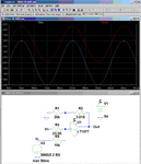
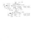
There are several options of the circuit, two are shown. The first is a ordinary single-phase rectifier followed by a single-supply op amp. The other uses a double-supply (ordinary) op amp.
One question remains: how fast your ADC should respond to AC voltage?
The feedback capacitor will act as a low-pass filter, so the ADC will read the DC voltage with AC ripple. Depending on the refresh rate of the ADC, the digitized output can oscillate as a beat between AC 50 or 60 Hz and the ADC refresh frequency. If you can refresh the ADC at the same rate as the AC frequency, the better result.
 

I second Cruwstchow's suggestion about using a precision fullwave rectifier. It requires two opamps.

There are precision halfwave rectifiers, but for a given ripple level, it will settle twice as slow.

Using two opamps is no big deal, as you can get dual opamps at the same cost a single opamp and in the same 8-pin IC package.
 

Below is a precision rectifier circuit with filter that should do what you want. It eliminates the offset problems of standard rectifier circuits. It operates from a single 5V supply and uses a quad op amp.

Edit: You may want to reduce the gain slightly so that the maximum output voltage is somewhat less than 3.5V to avoid saturating the A/D input.

Precision Rectifier.gif
 
Last edited:

Thanks for the replies.

I'm not 100% clear about two things,
1)is it really necessary to rectify the signal?
2)why can't i just add an offset? this is so that I still maintain the original sinusoidal signal just with offset and with a peak-peak of 3.5V
 
Last edited:

If you don't need DC then you don't have to rectify the signal, you can just offset and amplify the signal, and read the AC voltage. For reasonably accurate measurement, the ADC sample rate should be at least 10 times the frequency of the signal you are sampling (for example >500 samples/sec for a 50Hz signal). From those samples you can calculate the true RMS value if you like.

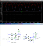
Below is a circuit to provide offset and gain.

NI Amp with offset.gif
 
View attachment 94787[/QUOTE]

Thanks, my system is running smooth now.

- - - Updated - - -

If you don't need DC then you don't have to rectify the signal, you can just offset and amplify the signal, and read the AC voltage. For reasonably accurate measurement, the ADC sample rate should be at least 10 times the frequency of the signal you are sampling (for example >500 samples/sec for a 50Hz signal). From those samples you can calculate the true RMS value if you like.

Below is a circuit to provide offset and gain.

View attachment 94787

Thanks, my system is running smooth now.
 

Status
Not open for further replies.

Similar threads

Part and Inventory Search

Welcome to EDABoard.com

Sponsor

Back
Top