logintojalluri
Newbie level 5
hi
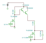
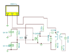
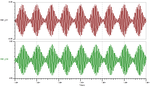
i am little bit knew about electronics basics.i am really mad about how to design ask modulator . from about 2 weeks i tried some circuits available in google. but i couldn't get the required rectangular output. plz anybody give me awareness about how to design ask modulator circuit . i have to give the ask input to class e amplifier.
thanks in advance