Ricardo Peterson
Newbie level 1
Hello,
I am currently using Allegro Design Entry CIS, and I'm rather new to it.
I built a double pulse test circuit but I am having trouble simulating it. I created a new simulation profile and ran a transient analysis to 15us with a max step size of 10ns.
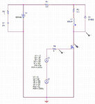
Upon simulating the circuit (and I'm not expecting correct results the first time), I get all of these floating nodes. My circuit is grounded as you can see in the schematic I attached here.
Any thoughts? Here are the floating node errors

- - - Updated - - -
Okay so I got it fixed, except for this error:
ERROR(ORPSIM-15141): Less than 2 connections at node N03994.
:/
I am currently using Allegro Design Entry CIS, and I'm rather new to it.
I built a double pulse test circuit but I am having trouble simulating it. I created a new simulation profile and ran a transient analysis to 15us with a max step size of 10ns.
Upon simulating the circuit (and I'm not expecting correct results the first time), I get all of these floating nodes. My circuit is grounded as you can see in the schematic I attached here.
Any thoughts? Here are the floating node errors
**** 06/30/13 13:32:00 ***** PSpice 16.6.0 (October 2012) ***** ID# 0 ********
** Profile: "SCHEMATIC1-sim1" [ C:\USERS\RICARDO\DROPBOX\REU\CADENCE\Run2\simulation 2-PSpiceFiles\SCHEMATIC1\sim1.sim ]
**** CIRCUIT DESCRIPTION
******************************************************************************
** Creating circuit file "sim1.cir"
** WARNING: THIS AUTOMATICALLY GENERATED FILE MAY BE OVERWRITTEN BY SUBSEQUENT SIMULATIONS
*Libraries:
* Profile Libraries :
* Local Libraries :
* From [PSPICE NETLIST] section of C:\Users\Ricardo\AppData\Roaming\SPB_Data\cdssetup\OrCAD_PSpice/16.6.0/PSpice.ini file:
.lib "nom.lib"
*Analysis directives:
.TRAN 0 15u 0 10n
.OPTIONS ADVCONV
.PROBE64 V(alias(*)) I(alias(*)) W(alias(*)) D(alias(*)) NOISE(alias(*))
.INC "..\SCHEMATIC1.net"
**** INCLUDING SCHEMATIC1.net ****
* source SIMULATION 2
V_V3 N03321 N03960
+PULSE -2 20 2u 10n 10n 8u 2000u
V_V1 N03029 GND_POWER 800Vdc
R_R2 N03787 N03029 1 TC=0,0
V_V2 N03960 GND_POWER
+PULSE 0 22 12u 10n 10n 2u 2000u
C_C1 GND_POWER N03787 2m TC=0,0
L_L1 N03329 N03713 856uH
R_R1 N03029 N03129 0.5 TC=0,0
R_R3 N03713 N03129 0.3 TC=0,0
R_R4 N03321 N03994 6 TC=0,0
D_D1 N03329 N03129 D10D2
**** RESUMING sim1.cir ****
.END
ERROR(ORPSIM-15141): Less than 2 connections at node N03994.
ERROR(ORPSIM-15142): Node N03321 is floating
ERROR(ORPSIM-15142): Node N03960 is floating
ERROR(ORPSIM-15142): Node N03029 is floating
ERROR(ORPSIM-15142): Node GND_POWER is floating
ERROR(ORPSIM-15142): Node N03787 is floating
ERROR(ORPSIM-15142): Node N03329 is floating
ERROR(ORPSIM-15142): Node N03713 is floating
ERROR(ORPSIM-15142): Node N03129 is floating
ERROR(ORPSIM-15142): Node N03994 is floating

- - - Updated - - -
Okay so I got it fixed, except for this error:
ERROR(ORPSIM-15141): Less than 2 connections at node N03994.
:/