Welcome to our site! EDAboard.com is an international Electronics Discussion Forum focused on EDA software, circuits, schematics, books, theory, papers, asic, pld, 8051, DSP, Network, RF, Analog Design, PCB, Service Manuals... and a whole lot more! To participate you need to register. Registration is free. Click here to register now.
Open loop gain >>> closed loop gain, so the -input tracks the + input. You can derive this with feedback theory.
You can also imagine it. When the output voltage is at 1V and the open loop gain 100k, voltage between input terminals of opamp will be 10uV. therefore there is virtually no voltage across +input and -input. AC current that goes into +input will be very small, hence the input impedance will be very high.
You should think of MOhms, so the additional series resistors are only there to confuse you. An exact value can only be determined when diving fully into the opamp characteristics as actual input impedance will be determined by non-ideal behavior of the opamp.
As said by WimRfP,the additional series resistors are only there to confuse you & accurate value would depend on non-ideal characteristics.
But for a rough approximate,
Input impedance is a differential quantity dV/dI rather than the ratio of input voltage and current V/I.
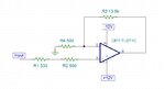
The shown multimeter measurement will mainly reflect the OP input current in combination with the meter's test voltage.
The real impedance will be around the datasheet value of 10E12 ohms and not depend much on the amplifier closed loop gain as long as feedback is keeping the differential input voltage small. This can be concluded by looking at the circuit of TL071 input stage.
the input resistance at non-inverting amplifier shows the internal resistance of the signal source (or the driving circuit), because this image may from some book, and author do care about each point.
The input resistance at inverting (-ve) terminal and the feedback resistance is for adjusting the gain as long as the op amp is in linear region, however the internal resistance is approx equal to the input impedance of the op amp because it is too large (one of important properties of op amp)compared to the other resistances.
This site uses cookies to help personalise content, tailor your experience and to keep you logged in if you register.
By continuing to use this site, you are consenting to our use of cookies.