Continue to Site

Welcome to EDAboard.com

Welcome to our site! EDAboard.com is an international Electronics Discussion Forum focused on EDA software, circuits, schematics, books, theory, papers, asic, pld, 8051, DSP, Network, RF, Analog Design, PCB, Service Manuals... and a whole lot more! To participate you need to register. Registration is free. Click here to register now.

10KVA inverter Design Project

Status
Not open for further replies.

Ogu Reginald

Full Member level 6
Joined
Oct 7, 2011
Messages
369
Helped
47
Reputation
94
Reaction score
46
Trophy points
1,308
Location
Nigeria
Activity points
3,391
Hi, I am working on a project that involves 10KVA inverter and I will like to use this medium to share my expereince/knowledge on inverter. Please correct me where possible if I make mistake.
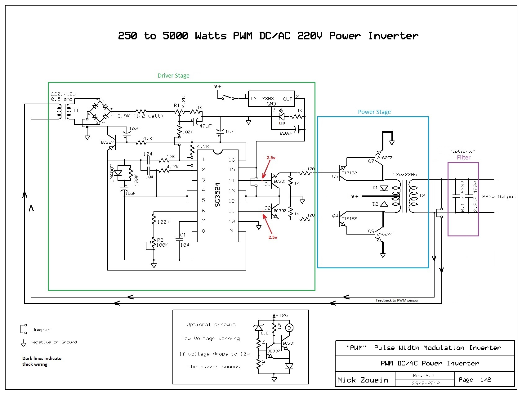
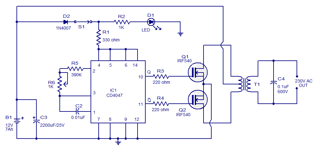
1. Every inverter has an oscillatory circuit, current handling/amplification circuit(transistors or other semi conductor) and the output transformer.
2. The output power of an invereter is directly proportional to the size and numbers of semi conductors used and also to the size of the output transformer.

I am confused on the IC to use for the oscillatory circuit? please help me with a good IC also state the reason for choosing the IC.

- - - Updated - - -

Also help me with the type of transistor to use whether (BJT or MOSFET) give reason for choosing each one and tell me how many will be sufficient for the design. Adding circuit diagrams and project reports will be of great help, thank you.
 

hi ogu reginald
first of all , i will give u the overview of the inverter ,,
1) linear transformer based inverter

now i will tell u in detail about this type
-- LINEAR TRANSFORMER BASED INVERTER--
In this type of inverters ,,first of all 12vdc is converted into 12vac(square wave or modified sine wave or pure sine wave) now this 12vac is supplied to a step up iron core transformer ,which will give output around 220vac,,now the question arises that how much load u have to put on this 220vac ,,the answer is suppose your load is 500watts ,,so you have to chosse a stepup transformer of rating 12/220v 600VA..,,now again one question is arising in ur mind i.e. why 600VA? it is because in a simple alternating current (AC) circuit consisting of a source and a linear load, both the current and voltage are sinusoidal. If the load is purely resistive, the two quantities reverse their polarity at the same time. At every instant the product of voltage and current is positive, indicating that the direction of energy flow does not reverse. In this case, only active power is transferred.
If the loads are purely reactive, then the voltage and current are 90 degrees out of phase. For half of each cycle, the product of voltage and current is positive, but on the other half of the cycle, the product is negative, indicating that on average, exactly as much energy flows toward the load as flows back. There is no net energy flow over one cycle. In this case, only reactive energy flows—there is no net transfer of energy to the load.
Practical loads have resistance, inductance, and capacitance, so both active and reactive power will flow to loads. apparent power is the magnitude of the vector sum of active and reactive power. Apparent power is the product of the root-mean-square of voltage and current.

till now u have selected the required transformer for ur inverter, now we will do some calculations on measuring the transformer's input current so that u can make a power stage which will be capable of handling that much current
as we have selected a 600VA centertap(in our case ,u can select a 100VA also), as you are a beginner u can start with 100VA,,but u can also disagree with me.. now come on to the point ,,as we hve selected 600VA transformer so at full load the input current will be approx 600/12 i.e 50ampere .
now our aim is to make a power stage of inverter that can handle greater than 50 ampere(as a safe side) using MOSFETs.
now we have to drive these power mosfets using a driver circuit ,,this driver circuit will drive the mosfets in a pushpull topology,
if u want that ur output voltage should be constant i.e. does not decrease when the load is increased then you can also use a feedback network, let me clear you this in detail..suppose u hve made ur inverter which is giving 220vac at the output with no load, now when u connect a load (say 100 watt bulb) then the output voltage will not going to equal to 220v .it will be less than 220v ..but our aim is to keep the voltage constant at the output ..so there is need of some feedback network... now this feedback will control the dutycycle of the PWM signal which is driving the mosfets...suppose when there is no load then duty cycle is65% now as u connect the load ur duty cycle will increase say (80%) SO AS to keep the output voltage constant... i am giving u a circuit schematic
in the below figure u hve to replace the the power bjt TIP122 with power mosfet ,,.u can use irfz48n or irfz44n ,,just connect a small value(4.7 to 47 ohm) resistance between pin 11 and gate terminal ,,,,and also b/w pin 14 and gate terminal,,,, also put a 2k resistor b/w gate and source,, with source grounded...


if u want a simple schematic i.e without feedback then u can go with this schematic below


--BawA--
 
There is one thing I have figure out, almost all the inverter circuit I see a capacitor is always connected to the output terminal of the transformer why?
So if I want to increase my output power, what I need to do is add some transistors and then change my transformer to a bigger one right.
 

The capacitor is used as a filter and it is optional..
And if u want to increase output power u have to use such mosfet which can handle ur input desired current .I.e the current flowing from drain to source of the mosfet. Now the maximum input current will depend on the output load .suppose u want to to run an air conditioner (1800 watts approx) then u have to choose a transformer of rating 2000va
. Now at full load your output current will be
2000/220 ampere =9 ampere and ur input current in transformer will be 2000/12 =166 ampere .so u hve to choose a mosfet which can handle a drain to source current greater than 166ampere.
Irf3205 can handle approx 100ampere so u can use 2 irf3205 in parallel...
 

With what you just said, asuming the output power to be 10KVA. Going by what you just did, The output current will be approximately 100AMPS. And the current going to the input of the transformer will be 850AMPS (I allowed tolerance for the value of the two currents in Question). Check the calculations. I want to use IRF150 which can handle 40AMPS, So should I use 25 Pieces of the MOSFET in parallel to provide the desired current? And the 25 pieces will be 25 up and 25 down.
 
  • Like
Reactions: erdian

    erdian

    Points: 2
    Helpful Answer Positive Rating
With what you just said, asuming the output power to be 10KVA. Going by what you just did, The output current will be approximately 100AMPS. And the current going to the input of the transformer will be 850AMPS (I allowed tolerance for the value of the two currents in Question). Check the calculations. I want to use IRF150 which can handle 40AMPS, So should I use 25 Pieces of the MOSFET in parallel to provide the desired current? And the 25 pieces will be 25 up and 25 down.
H! Ogu Reginald
No you will not use 12v-0-12v ,because the current is too high(850Amps).use 96v centre tap(96v-0-96v) for 10kva .10.6kva, input current 109.4amp .Yes irf150N can haddle 40amps. ,8pieces connected in parallel per side
 

For 10kva u should not use 12v battery . U must use atleast 48v battery ( four 12 v battery in series)
Now your inuput current will be 10000/48
Which will be 208ampere . And as I already said that irf3205 can handle 100 ampere current .so you should use 4 irf3205 for up and 4 irf3205 for down to be safe side.
With proper heat sink..
 

How many amps does a battery of 12V 65Ah produce and how long does it take for it to be fully charged with 5Amps?
Which IC should I use for the oscillator side? Is it SG5324 OR CD4047?
Help me select one and give me the working circuit diagram of the one choosen and the reason for choosing any one. Is the MOSFETs goíng to be drived with a BJT?
 
Last edited:

For 10kva u should not use 12v battery . U must use atleast 48v battery ( four 12 v battery in series)
Now your inuput current will be 10000/48
Which will be 208ampere . And as I already said that irf3205 can handle 100 ampere current .so you should use 4 irf3205 for up and 4 irf3205 for down to be safe side.
With proper heat sink..
Dear,
I think you failed to realize that IRF3205 are not suitable for 48 v Inverter operation as they have low voltage rating...Mosfets in a inverter operating in Push-Pull ( with 48V input) mode will see 96 v on Drains...
 

How many amps does a battery of 12V 65Ah produce and how long does it take for it to be fully charged with 5Amps?
Which IC should I use for the oscillator side? Is it SG5324 OR CD4047?
Help me select one and give me the working circuit diagram of the one choosen and the reason for choosing any one. Is the MOSFETs goíng to be drived with a BJT?
Mr ogu, i will not advice you yo start with very high power inverter for starting just carefully understand how inverter works very well before you think of buiding one, i am not trying to discourage you for building the inverter but kindly see professional on it so that he can advice you on what to do...where are you in 9ja?
 

Prove yourself on what you just said.

- - - Updated - - -

Mr ogu, i will not advice you yo start with very high power inverter for starting just carefully understand how inverter works very well before you think of buiding one, i am not trying to discourage you for building the inverter but kindly see professional on it so that he can advice you on what to do...where are you in 9ja?

I am seeking the advice of professionals that is what I am doing online. Unless you want to tell me that you are not a professional the the thread is not for you. You didn't answer any of my questions rather you deviated to what I don't know. Answer my questions if you wish but if you don't want to then leave the thread thank you.

- - - Updated - - -

Dear,
I think you failed to realize that IRF3205 are not suitable for 48 v Inverter operation as they have low voltage rating...Mosfets in a inverter operating in Push-Pull ( with 48V input) mode will see 96 v on Drains...

Please i want you to prove the authenticity of what you just said beyond all reasonable doubt. Is the information that you just gave coming from the datasheet of IRF3205 or from where?
 

Prove yourself on what you just said.

- - - Updated - - -


I am seeking the advice of professionals that is what I am doing online. Unless you want to tell me that you are not a professional the the thread is not for you. You didn't answer any of my questions rather you deviated to what I don't know. Answer my questions if you wish but if you don't want to then leave the thread thank you.

- - - Updated - - -


Please i want you to prove the authenticity of what you just said beyond all reasonable doubt. Is the information that you just gave coming from the datasheet of IRF3205 or from where?

Dear,
Did you ever had a chance to read IRF3205 Datasheet ? the datasheet clearly states under ABSOLUTE MAXIMUM RATINGS that VDS(Voltage from Drain to Source) maximum == 55 Vdc.
3205.jpg

Apart from this i would like you to behave in good manner...as what Kabeer said was also a good advice for a starter like you...what he advised is a word of caution from a PROFESSIONAL which only a PROFESSIONAL can give...sometimes even experts are strucked in a small power circuitry design...(leave alone the huge 10KVA design).

And one more thing..we all are not here to prove us...if you really want to authenticate what we all suggest ..the you should go and download texts/datasheets/documents/technical papers ..study them and then get back to us if you finds our information misleading...its just very easy to say "Prove yourself on what you just said."

No body is pulling you back here or trying to discourage you..but trying to lead you to the best way..Hope you can understand what i mean.
 

In push pull stage mosfets are alternately switched on and off, reversing the current in the transformer. So current will be drawn from the line during both halves of the switching cycle. . And irf3205 can handle vds 55vdc that is drain voltage 55v with respect to source. And in your case source is grounded ..and at one instant of time only one mosfet bank will be on. So with respect to to source drain will not exceed more than 48v. .

- - - Updated - - -

In push pull stage mosfets are alternately switched on and off, reversing the current in the transformer. So current will be drawn from the line during both halves of the switching cycle. . And irf3205 can handle vds 55vdc that is drain voltage 55v with respect to source. And in your case source is grounded ..and at one instant of time only one mosfet bank will be on. So with respect to to source drain will not exceed more than 48v at a particular instant of time.
 

So with respect to to source drain will not exceed more than 48v.
I presume you are talking about a transformer Push-pull output stage as in your post #2. Maximum Vds with an ideal transformer will be double supply voltage. A real transformer will however generate additional overvoltage due to leakage inductance between both primary windings. So there should be a certain overhead in Vds rating, e.g. using 200V transistor for 48V battery voltage. Otherwise the transistors will be driven into avalanche breakdown during each switch-off. Modern MOSFETs have some avalanche capability, but losses will be respectively high.

Apart from keeping sufficient voltage rating you shouldn't misunderstand maximum continuous current rating, e.g. 110A for IRF3205 as a reasonable choice for operation current in aparticular application. Transistor power dissipation according to Rdson and overall efficiency have to be considered, too.

For the rest, I agree with the comments of aashitech and kabeer02.
 

After all the discussions, I have decided to use IRF150 and the attached picture is the circuit diagram of 10KVA inverter. I am using 48V battery(4 X 12 V). I simulated the circuit on multisim and on proteus, it is working perfectly well. Please look at the diagram critically and make some suggestions where neccessary. Thank you.
 

hello Mr Ogu contact me on this line for details on any inverter construction am a Nigerian by nationality 07030663376
 

After all the discussions, I have decided to use IRF150 and the attached picture is the circuit diagram of 10KVA inverter. I am using 48V battery(4 X 12 V). I simulated the circuit on multisim and on proteus, it is working perfectly well. Please look at the diagram critically and make some suggestions where neccessary. Thank you.
Hi,
For 10Kw in 48V the current will 208A it is very difficult to wire the power transistors , I recommend you to at least double the Battery voltage and select a suitable Mosfet
 

Yes with 48V the current is 208Amps but the MOSFET IRF150 is capable of handling 40Amps so I am using 6pieces (6X40= 240Amps) at either side making it a total of 12pieces.
During my simulation i figured out that the output voltage decreased when I connected some loads. Please can someone tell me what to do so that the output of the inveretr will remain constant either at no load and at full load.
I have been trying to upload the circuit diagram but the network here is very bad. I will keep on trying.
 

10kva 48v inverter is not a good design.Use 96v and above.Modify the first cct posted by BawA.The cct will give you all you want.(constant voltage with load and without load.)
 
Last edited:

Status
Not open for further replies.

Part and Inventory Search

Welcome to EDABoard.com

Sponsor

Back
Top