edwina
Newbie level 3
Hi all,
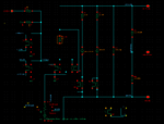
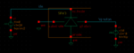
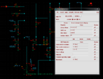
I'm implementing a SPAD model(base on: SPICE modeling of single photon avalanche diodes. by F. Zappa∗, A. Tosi, A. Dalla Mora, S. Tisa and published in Sensors and Actuators A 153 (2009) on pages 197–204) and the problem is in a swith out of the analogLib of Cadence (in combination with Spectre) that should simulate the selfsustainability of a above breakdown reversed baised diode. See circuit.PNG for the whole circuit and "switch properties.PNG" for the properties of the switch that troubles me. In "setup.PNG" the setup of the model of "circuit.PNG" is showed (in short: anode and substrate are grounded, cathode is connected to a ramp (20V -> 25V in 10u seconds) and photon is connected to a pulse source (10Vpk-pk. Period: 2us, dutycycle 50% and a delay of 500ns).
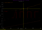
Because the switching voltage of the troubeling switch (W3) is 100uV, you would expect that the switch stays closed when the voltage across Rsense (in orange in "simulation results..PNG") is more than 100uV. However (as can be seen in "simulation results..PNG" (the colors of "simulation results..PNG" are matched with "circuit.PNG")) this doesn't happen.
At first there won't flow any current (and so the voltage drop across Rsense is zero). This is because switch S1 is closed intil Vcathode-Vanode > 21.54 V. After that moment in time, Vtrigger won't be grounded and so switch Strig will be in opperation mode (this can be seen in the simulation results by the first non-zero slope of the voltage across Rsense and the first rising egde of Vtrigger (red in the simulation results)). After the second pulse (indicated by the indicater in the simulation results) the voltage across Rsense is already ~1.71mV, so more then 100uV and so switch W3 should be closed (and stay closed) resulting in a "self sustaining avalanche". When a self sustaining avalanche occures, the current through switch Strig and W3 should be continuous (ignoring the resistance of the switches) and so the voltage drop over Rsense should be continuous to. However, as can be seen in "simulation_results..PNG", is isn't.
The weird thing is that after the next pulse of Vin, the switch stays closed.
Does someone recognize this behaviour or experienced it before and know a workaround of a fix for it?
Oowja: the weird thing in the middel-botom of the circuit is a piecewise linear voltage controlled voltage source in series with a piecewise linear voltage controlled resistor (as suggested in SPICE modeling of single photon avalanche diodes. by F. Zappa∗, A. Tosi, A. Dalla Mora, S. Tisa). It just models the non linear current behaviour of an reversed biased diode in avalanche. So when Vin (Vanode-Vcathode) rises, the current through this component rises. It works fine so I don't expect this guy is the problem.
With kind regard,
Edwin
P.s. I also build the the setup with Rsense, the two parallel switches and a current limitation resistor to check if the concept works (in Cadence) and that one just worked fine.
I'm implementing a SPAD model(base on: SPICE modeling of single photon avalanche diodes. by F. Zappa∗, A. Tosi, A. Dalla Mora, S. Tisa and published in Sensors and Actuators A 153 (2009) on pages 197–204) and the problem is in a swith out of the analogLib of Cadence (in combination with Spectre) that should simulate the selfsustainability of a above breakdown reversed baised diode. See circuit.PNG for the whole circuit and "switch properties.PNG" for the properties of the switch that troubles me. In "setup.PNG" the setup of the model of "circuit.PNG" is showed (in short: anode and substrate are grounded, cathode is connected to a ramp (20V -> 25V in 10u seconds) and photon is connected to a pulse source (10Vpk-pk. Period: 2us, dutycycle 50% and a delay of 500ns).
Because the switching voltage of the troubeling switch (W3) is 100uV, you would expect that the switch stays closed when the voltage across Rsense (in orange in "simulation results..PNG") is more than 100uV. However (as can be seen in "simulation results..PNG" (the colors of "simulation results..PNG" are matched with "circuit.PNG")) this doesn't happen.
At first there won't flow any current (and so the voltage drop across Rsense is zero). This is because switch S1 is closed intil Vcathode-Vanode > 21.54 V. After that moment in time, Vtrigger won't be grounded and so switch Strig will be in opperation mode (this can be seen in the simulation results by the first non-zero slope of the voltage across Rsense and the first rising egde of Vtrigger (red in the simulation results)). After the second pulse (indicated by the indicater in the simulation results) the voltage across Rsense is already ~1.71mV, so more then 100uV and so switch W3 should be closed (and stay closed) resulting in a "self sustaining avalanche". When a self sustaining avalanche occures, the current through switch Strig and W3 should be continuous (ignoring the resistance of the switches) and so the voltage drop over Rsense should be continuous to. However, as can be seen in "simulation_results..PNG", is isn't.
The weird thing is that after the next pulse of Vin, the switch stays closed.
Does someone recognize this behaviour or experienced it before and know a workaround of a fix for it?
Oowja: the weird thing in the middel-botom of the circuit is a piecewise linear voltage controlled voltage source in series with a piecewise linear voltage controlled resistor (as suggested in SPICE modeling of single photon avalanche diodes. by F. Zappa∗, A. Tosi, A. Dalla Mora, S. Tisa). It just models the non linear current behaviour of an reversed biased diode in avalanche. So when Vin (Vanode-Vcathode) rises, the current through this component rises. It works fine so I don't expect this guy is the problem.
With kind regard,
Edwin
P.s. I also build the the setup with Rsense, the two parallel switches and a current limitation resistor to check if the concept works (in Cadence) and that one just worked fine.