blueray
Newbie level 3
Hi all
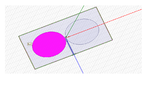
i am working on printed ellipse dipole antenna which s working on 900 Mhz . But i have some boundaries the lenght of the dipole must be max 72 mm. i have simulated on HFSS but i cant see a good returm loss for this . i have -2 or -3 db return loss on 900 Mhz .So how can i decrease the rezonance frequency without increasing the lenght of the dipole ?
thanks for your helping
")