Continue to Site

Welcome to EDAboard.com

Welcome to our site! EDAboard.com is an international Electronics Discussion Forum focused on EDA software, circuits, schematics, books, theory, papers, asic, pld, 8051, DSP, Network, RF, Analog Design, PCB, Service Manuals... and a whole lot more! To participate you need to register. Registration is free. Click here to register now.

Help needed in Oscillator

Status
Not open for further replies.

Ow@i$

Advanced Member level 1
Joined
Sep 18, 2012
Messages
413
Helped
78
Reputation
156
Reaction score
75
Trophy points
1,308
Location
Pakistan
Activity points
3,430
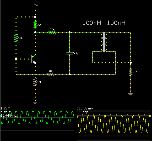
Following is the proteus design of the oscillator it works fine in simulation .. but not working in hardware.. it doesn't oscillate....!! what could be the reason do i need a voltage signal to kick start the oscillation???

Untitled.png

any help appreciated !!

the frequency if 10.6Mhz
 
Last edited:

Sometimes an oscillator will not get going, unless it has exactly the right amount of bias (no more, no less) at the transistor/ mosfet / jfet.

Suggestion: install a potentiometer (10k ohm) to adjust the bias.

Per screenshot:


This appears to be a Hartley type. In the same family anyway.

I made a change or two (in addition to the potentiometer).
I substituted a resistor for the leftmost capacitor. Up until then I was not able to obtain reliable oscillations. For the same reason I used a transistor instead of a jfet.

Frequency is about 10 MHz.
 

I don't agree that the circuit works fine, because it produces rather distorted waveforms in simulation. There are tons of better oscillator circuits.

Possible reasons why it might not work in real life:

- FET IDSS/VGSS is too high for the circuit dimensioning. 2N3819 has a rather wide parameter range. Check for sufficient Vds.
- The inductors have too low self resonance frequency respectively too high winding capacitance for the intended frequency range. Check the specification.
 

Although schematics may portray the two coils as separate components, and although it is possible to obtain sustained oscillations that way...

The Hartley oscillator typically has the two coils constructed as a tapped inductor. The effect is to strengthen current around the LC loop, thus encouraging oscillations from the start.

Screenshot:


I chose a transformer to simulate the tapped inductor. It's important to reverse the polarity of one winding.

It took me a while to adjust this simulation so as to yield sustained oscillations. Stagnation is easy in this schematic as well as the one in the OP.
 

In terms of component costs, a colpitts oscillator should be considered, too.
 

Thank You all for your precious feedback !!

I tried to make my original design work but it didn't .. so I sort of played with it, ended up in burning one FET anyhow the modified design worked perfectly on hardware as well as in simulations!!!

Here is the modified one!!

Untitled.png

Values were all taken randomly bcz typical formula didn't worked in this design... I can't justify my values mathematically but they are working perfectly and that is what i guess matters :)

I will appreciate if someone can come up with the mathematical equation to calculate oscillating frequency, it will help future designers as it is a very economical and easy to implement oscillator !!!
 

Status
Not open for further replies.

Similar threads

Part and Inventory Search

Welcome to EDABoard.com

Sponsor

Back
Top