Continue to Site

Welcome to EDAboard.com

Welcome to our site! EDAboard.com is an international Electronics Discussion Forum focused on EDA software, circuits, schematics, books, theory, papers, asic, pld, 8051, DSP, Network, RF, Analog Design, PCB, Service Manuals... and a whole lot more! To participate you need to register. Registration is free. Click here to register now.

Need Help! Audio Op-Amp

Status
Not open for further replies.

Ebonic

Junior Member level 2
Joined
Oct 14, 2011
Messages
24
Helped
1
Reputation
2
Reaction score
1
Trophy points
1,283
Location
USA
Activity points
1,539
Hi all


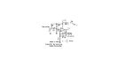
Having trouble configuring this op-amp in my project.And get it to work correctly.

**broken link removed**
Using op-amp LMV796 from TI.

In a Non-inverting configuration.And it must be in the Non-inverting configuration
So the signal does not attenuate from the electret Mic.

The circuit is in figure 10 in the Datasheet.

I'm using a power supply of 3.6V to power the amp.
I want to use a variable pot for a gain of 0-20.

Then i want to connect the amp to a 9170 DTMF decoder.

HT9170B  Circuit..PNG
 

The attachment doesn't open for me. Why do you think it has to be non-inverting? An inverting amplifier still amplifies, it just turns the output waveform upside down. The DTMF decoder is a standard circuit and works well. Make sure you use the correct crystal/resonator frequency though or it will not recognize the correct tones.

Brian.
 

The attachment doesn't open for me. Why do you think it has to be non-inverting?


The reason for the non-inverting the mic has a high impedance.And if it in the inverting configuration which has a low inpedence of 1K
it will attenuate.This is what i found out.

The crystal is a 3.5795mhz I'm using it is the correct one.
Can you help.


The attachment open for me click on the attachment.Its a PDF Datasheet.
 

I had a quick look at the data sheet but I can't see anything that suggests it has low input impedance, in fact just the opposite. The input bias current is only a few pA so it should be possible to set the input impeadance extremely high. Regardless of that, an electret microphone has relatively low impedance and high output, it might even connect directly to the DTMF decoder without an additional amplifier. Don't forget there is already an amplifier inside the 8870.

Brian.


Op Amp LMV796.PNG Left click this image.

Enclosed is the amp.

Do i have this amp design correctly.If not.what do i need to omit or add
to the circuit. for this to work correctly for my project.

Then how do i connect it to the HT9170.In post #1,image.:-?
 
Last edited:

1. leave out the 100K resistor.
2. change the 120pF capacitor for about 100uF.
3. add a capacitor of 10uF across the amps supply pins, mounted as close as possible to them.

It should then work.

To hook it up to the 9170, connect the amp output pin to the input of the DTM schematic.

Brian.
 

I have chaged the 10K to a 20K pot for variable gain
increased the biasing values to 100K.Is that enough.
Added the 10uf cap on the supply pins.
For CC1 isn't 100uf to big what if i use 1000pf. would the larger cap filter out
the lower FQ.

Enclosed changed circuit.

Do i need to add a cap or 10K resistor to the output of the amp then connectto
the in put of the DTMF coder.
Which input do i connect to the noninverting input or the inverting input.
I assume it would be the Non-inverting.Don't know.

Do i need to add or omit the the circuit.
 

Attachments

  • Op-Amp  Circuit   2    eda.PNG
    Op-Amp Circuit 2 eda.PNG
    33.5 KB · Views: 137

You should read up on how an anplifier like this works so you understand what each of the components and values do.

Your new schematic is correct although why you want to run it from 3.6V when the DTMF IC needs 5V is unclear, they will both work fine from 5V so link their supply pins together. The detached 10uF capacitor is not needed, the one across the supply only has to span the + and ground pins.

The two 100K resistors are there to set the voltage on the output pin. Because they are the same value, the voltage at their junction with the IC will be at half the supply voltage and in this configuration it will make the output pin at half voltage too. This is ideal because it allows the output voltage to swing equally in both directions, toward ground and toward supply. Looking at it a different way, the output pin should be at 2.5V so it can theoretically go 2.5 above that (5V) or 2.5 below it (0V) giving you as much as 5V of signal but if the pin was at 1V, it could only go down as low as ground (0V) so the signal would have it's bottom clipped off.

It's an inverting configuration with feedback (= gain setting) controlled by the amount of signal fed back from the output to the inverting input. If you directly linked the output pin to the inverting input you would get a gain of x1 (same out as in) but if you reduce the amount of feedback the gain becomes higher. The resistors connected to the inverting inut are there to set the amount of feedback and therefore the gain. The capacitors have two jobs, the first is to block DC so the steady voltage on the inverting input comes only from the output pin, this stabilizes the operating conditions inside the amplifier IC. Their other job is to control the frequency response. Remember that capacitors have a property called reactance (symbol Xc) which is similar to resistance but it changes according to frequency, Xc = 1/(2 * pi * f * C), so as frequency increases the reactance falls. The capacitor between the output and inverting input (across your variable resistor) makes the gain lower as frequency increases and the one in the inverting input to ground makes the gain increase with frequency.

I leave it as an exercise for you to do: using the formula for Xc, and the formulas for resistors in series and parallel and assuming you can treat Xc as a resistor (almost true) work out what the feedback and gain are at different frequencies. The range you are interested in is from about 100Hz to 10KHz so pick some frequencies between them and draw a graph of the gain. It think that will explain why I consider the capacitor values to be wrong. Don't forget frequency units are Hz, capacitor values are in F and resistors are in Ohms.

Brian.
 

Your new schematic is correct although why you want to run it from 3.6V when the DTMF IC needs 5V is unclear


The HT9170 DTMF has a voltage range from 2.5V-5.5V its a cmos version of the 8870.Its a clone,with a wider voltage range.
Plus i use single AA cells that are 3.6-3.7 volts for my projects.I don't need to buy whole bunch of batteries for 5V.
And they last alot long.At 2400mAH at 100mA or less.I trying to keep my projects small but simple.As a beginner.

Im not that good at using these formula's.Is there a better and easier way to understanding them. Im just starting out.

Any tutorials you know of that makes it simple for a beginner like myself could understand opamps and these formula's stuff.
Pi is 3.142 the rest is not understandable. in the Formula.

How do you get 100Hz to 10KHz with the gain at 21 and using a 20K and a 1k FEEDBACK resistors.Just try to understand this.


Thank!
 

Actually, the 8870 is CMOS too but uses normal TTL level voltages. I used to work next door to the factory that made them so I have a few samples!

Be careful that you only interface it to low voltage digital devices.

For the values, you already know how to work out the gain from the feedback resistors, just imagine the capacitors are like resistors that only conduct audio and not DC. Just as resistors in parallel have a lower resistance than each individually, so do resistors and capacitors in parallel. So a capacitor in the feedback from output to -input will appear as a resistor across the existing one (your potentiometer) and reduce its effective value. As the frequency increases the capacitor effectively has less resistance so there is more feedback and the gain becomes less. In other words, a capacitor from the output to the inveting input makes the gain drop as frequency increases.

The other capacitor to ground does exactly the same, it's value drops as frequency increases but because its across the feedback it reduces it and makes the gain higher. So this capacitor makes the gain higher as the frequency increases.

You can see how the tone response can be changed by adjusting the capacitor values. However, you don't get a brick-wall response, it doesn't instantly lose gain at a particular frequency, it gradually changes so to set a response you have to decide at which frequencies the gain will have dropped by a certain amount. Your value of Cf sets the upper response so high that it falls well above the audible range, the original value you chose for CC1 gives a low frequency half-gain point of around 1.3MHz when you really want it to be around 100Hz!

Brian.
 

Status
Not open for further replies.

Part and Inventory Search

Welcome to EDABoard.com

Sponsor

Back
Top