Continue to Site

Welcome to EDAboard.com

Welcome to our site! EDAboard.com is an international Electronics Discussion Forum focused on EDA software, circuits, schematics, books, theory, papers, asic, pld, 8051, DSP, Network, RF, Analog Design, PCB, Service Manuals... and a whole lot more! To participate you need to register. Registration is free. Click here to register now.

[Moved] LPC2138 PWM to control servo motor

Status
Not open for further replies.

kodi.sudar

Member level 5
Joined
Dec 21, 2009
Messages
92
Helped
0
Reputation
0
Reaction score
0
Trophy points
1,286
Location
india
Activity points
1,849
Hi alex
nice work . I need to control the servo motor with the help of lpc2138 and i am trying to use pwm and i found your application it helps me a lot but the thing is the pwm generated fails to drive the servo. can you help me to assign the values for PWMMR0,PWMMR1,PWMMR2 registers, i am using pwm 2

Thanks
 

Re: ARM7 (LCP21xx, 23xx, 24xx) & cortexM (LPC17xx,13xx,11xx) register settings wizard

You should post your code so we can see what you are doing.
Also provide the clock info.

A schematic would also be nice
 

Re: ARM7 (LCP21xx, 23xx, 24xx) & cortexM (LPC17xx,13xx,11xx) register settings wizard

You should post your code so we can see what you are doing.
Also provide the clock info.

A schematic would also be nice

Code:
/************************************************************************************
   Code created using the ARMwizard, visit http://alexan.edaboard.eu 
************************************************************************************/

#include <LPC213x.h>


int main(void)
{
/*
    P0.0:  PORT0.0 (General purpose I/O)  Input
    P0.1:  PORT0.1 (General purpose I/O)  Input
    P0.2:  PORT0.2 (General purpose I/open-drain O)  Input
    P0.3:  PORT0.3 (General purpose I/open-drain O)  Input
    P0.4:  PORT0.4 (General purpose I/O)  Input
    P0.5:  PORT0.5 (General purpose I/O)  Input
    P0.6:  PORT0.6 (General purpose I/O)  Input
    P0.7:  PWM2 (Pulse Width Modulator output 2)
    P0.8:  PORT0.8 (General purpose I/O)  Input
    P0.9:  PORT0.9 (General purpose I/O)  Input
    P0.10:  PORT0.10 (General purpose I/O)  Input
    P0.11:  PORT0.11 (General purpose I/O)  Input
    P0.12:  PORT0.12 (General purpose I/O)  Input
    P0.13:  PORT0.13 (General purpose I/O)  Input
    P0.14:  PORT0.14 (General purpose I/O)  Input
    P0.15:  PORT0.15 (General purpose I/O)  Input
    P0.16:  PORT0.16 (General purpose I/O)  Input
    P0.17:  PORT0.17 (General purpose I/O)  Input
    P0.18:  PORT0.18 (General purpose I/O)  Input
    P0.19:  PORT0.19 (General purpose I/O)  Input
    P0.20:  PORT0.20 (General purpose I/O)  Input
    P0.21:  PORT0.21 (General purpose I/O)  Input
    P0.22:  PORT0.22 (General purpose I/O)  Input
    P0.23:  PORT0.23 (General purpose I/O)  Input
    P0.25:  PORT0.25 (General purpose I/O)  Input
    P0.26:  PORT0.26 (General purpose I/O)  Input
    P0.27:  PORT0.27 (General purpose I/O)  Input
    P0.28:  PORT0.28 (General purpose I/O)  Input
    P0.29:  PORT0.29 (General purpose I/O)  Input
    P0.30:  PORT0.30 (General purpose I/O)  Input
    P0.31:  PORT0.31 (General purpose O)  Output
    P1.16:  PORT1.16 (General purpose I/O)  Input
    P1.17:  PORT1.17 (General purpose I/O)  Input
    P1.18:  PORT1.18 (General purpose I/O)  Input
    P1.19:  PORT1.19 (General purpose I/O)  Input
    P1.20:  PORT1.20 (General purpose I/O)  Input
    P1.21:  PORT1.21 (General purpose I/O)  Input
    P1.22:  PORT1.22 (General purpose I/O)  Input
    P1.23:  PORT1.23 (General purpose I/O)  Input
    P1.24:  PORT1.24 (General purpose I/O)  Input
    P1.25:  POR11.25 (General purpose I/O)  Input
    P1.26:  PORT1.26 (General purpose I/O)  Input
    P1.27:  PORT1.27 (General purpose I/O)  Input
    P1.28:  PORT1.28 (General purpose I/O)  Input
    P1.29:  PORT1.29 (General purpose I/O)  Input
    P1.30:  PORT1.30 (General purpose I/O)  Input
    P1.31:  PORT1.31 (General purpose I/O)  Input
*/


    PINSEL0 = 0x00008000;     /* binary: 00000000_00000000_10000000_00000000 */
    IO0DIR = 0x80000000;     /* binary: 10000000_00000000_00000000_00000000 */
    PINSEL1 = 0x00000000;     /* binary: 00000000_00000000_00000000_00000000 */
    PINSEL2 = 0x00000000;     /* binary: 00000000_00000000_00000000_00000000 */
    IO1DIR = 0x00000000;     /* binary: 00000000_00000000_00000000_00000000 */

/******************************************************************************
                                    PWM
*******************************************************************************
   Counter Disabled,    Counter Reset=0,    PWM mode enabled
   Counter clk: 500 Hz, Counts every: 2 ms  (calculated with peripheral clock: 3MHz)
   MCR0.0 : reset, on compare match
   MCR0.1 : reset, on compare match
   MCR0.2 : reset, on compare match
   PWM frequency: 50 Hz
   PWM1: Single edge, set by MR0, reset by MR1, output disabled
   PWM2: Double edge, set by MR1, reset by MR2, output enabled
   PWM3: Single edge, set by MR0, reset by MR3, output disabled
   PWM4: Single edge, set by MR0, reset by MR4, output disabled
   PWM5: Single edge, set by MR0, reset by MR5, output disabled
   PWM6: Single edge, set by MR0, reset by MR6, output disabled
*/

    PCONP = (PCONP & 0x001817BE) | (1UL<<5);      /* Enable peripheral clock for PWM0 (default is enabled) */

    PWMTC = 0x00000000;     /* decimal 0 */
    PWMPR = 0x0000176F;     /* decimal 5999 */
    PWMMCR = 0x00000092;     /* binary: 00000000_00000000_00000000_10010010 */
    PWMMR0 = 0x0000000A;     /* decimal 10 */
    PWMMR1 = 0x00000001;     /* decimal 1 */
    PWMMR2 = 0x00000003;     /* decimal 3 */
    PWMMR3 = 0x00000000;     /* decimal 0 */
    PWMMR4 = 0x00000000;     /* decimal 0 */
    PWMMR5 = 0x00000000;     /* decimal 0 */
    PWMMR6 = 0x00000000;     /* decimal 0 */
    PWMPCR = 0x00000404;     /* binary: 00000000_00000000_00000100_00000100 */
    PWMTCR = 0x08;     /* binary: 00001000 */

   while(1)
  {
  
  
   }

}

i am using the code from AMR wizard i need to control the servo motor connected in PWM2 but the code fails to drive the motor.


Thanks
 

Re: ARM7 (LCP21xx, 23xx, 24xx) & cortexM (LPC17xx,13xx,11xx) register settings wizard

You have used peripheral clock: 3MHz , what is the core clock frequency?


The problem I see is that you are using a 20ms PWM with a 30% duty which is 6ms but usually servos need a pulse between 1-2ms

Anyway, this is an example with 60MHz cpu clock and 1/4 for PCLK

Code:
/******************************************************************************
                                    PWM
*******************************************************************************
   Counter Enabled,    Counter Reset=0,    PWM mode enabled
   Counter clk: 51,1945 KHz, Counts every: 19,53 us  (calculated with peripheral clock: 15MHz)
   MCR0.0 : reset, on compare match
   PWM frequency: 50,0435 Hz
   PWM1: Single edge, set by MR0, reset by MR1, output disabled
   PWM2: Single edge, set by MR0, reset by MR2, output enabled
   PWM3: Single edge, set by MR0, reset by MR3, output disabled
   PWM4: Single edge, set by MR0, reset by MR4, output disabled
   PWM5: Single edge, set by MR0, reset by MR5, output disabled
   PWM6: Single edge, set by MR0, reset by MR6, output disabled
*/

    PCONP = (PCONP & 0x001817BE) | (1UL<<5);      /* Enable peripheral clock for PWM0 (default is enabled) */

    PWMTC = 0x00000000;     /* decimal 0 */
    PWMPR = 0x00000124;     /* decimal 292 */
    PWMMCR = 0x00000002;     /* binary: 00000000_00000000_00000000_00000010 */
    PWMMR0 = 0x000003FF;     /* decimal 1023 */
    PWMMR1 = 0x00000000;     /* decimal 0 */
    PWMMR2 = 0x00000034;     /* decimal 52   gives about 1ms pulse*/  
    PWMMR3 = 0x00000000;     /* decimal 0 */
    PWMMR4 = 0x00000000;     /* decimal 0 */
    PWMMR5 = 0x00000000;     /* decimal 0 */
    PWMMR6 = 0x00000000;     /* decimal 0 */
    PWMPCR = 0x00000400;     /* binary: 00000000_00000000_00000100_00000000 */
    PWMTCR = 0x09;     /* binary: 00001001 */

The usable range to get 1ms-2ms pulses is about 52-102 (PWMMR2 value) but you can increase the usable range using higher PWMMR0 values (and lower PWMPR to maintain the 500HZ PWM period)


Thanks alex i understood and modified the code . But can you tell me for speed control ant timing to stop the motor and also to drive two motor simultaneously. i
tried by generating pwm in two channels but it didnt workout.

Thanks in advance
 
Last edited:

I'm not sure what you mean by speed control, the servo rotates to different position according to a pulse width between 1ms and 2ms.
What kind of servo do you have, what are the specs?

You can use multiple PWM channels , I don't see a problem in that.
 

I'm not sure what you mean by speed control, the servo rotates to different position according to a pulse width between 1ms and 2ms.
What kind of servo do you have, what are the specs?

You can use multiple PWM channels , I don't see a problem in that.

I am trying with proteus simulation (hobby servo).

but the thing is servo continuously run entire rotation (say 360' )for the given pulse and it stops . but i am trying to run it for certain angle according to the adc value.
 

But my code did that.
Post your code and tell me what is the core frequency and what divider you have for the PCLK
 

But my code did that.
Post your code and tell me what is the core frequency and what divider you have for the PCLK
Code:
#include <LPC213x.h>

void adc_ini();
void adc_data();
void pwm();
void motor();

unsigned long val,adc_val;
float y,s,v,m;
unsigned long angle,b;

int main(void)
{
	 while(1)
  {
	
		adc_ini();
		adc_data();
		pwm();
		//motor();

    PINSEL0 = 0x00028000;     /* binary: 00000000_00000010_10000000_00000000 */
    IO0DIR = 0x80000000;     /* binary: 10000000_00000000_00000000_00000000 */
    PINSEL1 = 0x01000000;     /* binary: 00000001_00000000_00000000_00000000 */
    PINSEL2 = 0x00000000;     /* binary: 00000000_00000000_00000000_00000000 */
    IO1DIR = 0x00000000;     /* binary: 00000000_00000000_00000000_00000000 */

  
		/* angle calculation */
					m=(3.3/1023);/*3.3/1023 for adc conversion*/
					y=1.65;/*offset voltage */	
					s=0.8;/*sensitivity 800mv/g*/
					b=57.295;/* pi/180 for radian to degree conversion */
					/* formula tetha= arcsin( (vout - voffset)/sensitivity) */ 
					v=asin(((adc_val*m)-y)/s);
					angle=v*b;
  
   }

}


void adc_ini(void)
{

/******************************************************************************
                                     ADC0
*******************************************************************************
   ADC operational
   ADC clk: 3 MHz  (calculated with peripheral clock: 3MHz)
   ADC rate: 272.7273 Ksamples/sec
   Manual mode, 11 clocks / 10 bit accuracy
   Start conversion now.
*/

    PCONP = (PCONP & 0x001817BE) | (1UL<<12);      /* Enable peripheral clock for ADC0 (default is enabled) */
		AD0INTEN = 0x00000000;     /* binary: 00000000_00000000_00000000_00000000 */
    AD0CR = 0x01200002;     /* binary: 00000001_00100000_00000000_00000010 */

}

void adc_data(void)
{
					//AD0CR  |= 0x01000000;                   /* Start A/D Conversion               */
					while((AD0DR & 0x80000000)==0); //until bit 31 is high (DONE)
					val = AD0DR; //read a/d data register
					adc_val = ((val >> 6) & 0x3FF);    // Extract AD result
 } 
 
 
 void pwm(void)
 {

/******************************************************************************
                                    PWM
*******************************************************************************
   Counter Enabled,    Counter Reset=0,    PWM mode enabled
   Counter clk: 50 KHz, Counts every: 20 us  (calculated with peripheral clock: 3MHz)
   MCR0.0 : reset, on compare match
   PWM frequency: 50 Hz
   */

    PCONP = (PCONP & 0x001817BE) | (1UL<<5);      /* Enable peripheral clock for PWM0 (default is enabled) */

    PWMTC = 0x00000000;     /* decimal 0 */
    PWMPR = 0x0000003B;     /* decimal 59 */
    PWMMCR = 0x00000002;     /* binary: 00000000_00000000_00000000_00000010 */
    PWMMR0 = 0x000003E8;     /* decimal 1000 */
    PWMPCR = 0x00001400;     /* binary: 00000000_00000000_00010100_00000000 */
    PWMTCR = 0x09;     /* binary: 00001001 */
    motor();
}

void motor(void)
{
      if(angle > 10)
	  {
	     PWMMR2 = 0x0000004C;   
	     PWMMR4 = 0x0000004A;   
		}
}

Your code was working and i modified the code according to my need. but it fails to work when i change the adc input (just for exact input 1.79v)
what modification should i do to achieve that.


Thanks
 

for the third time, what is you core clock frequency and what is your pclk divider?

- - - Updated - - -

The code inside a while loop is constantly repeated, what is the reason for having the ADC initialization, pwm initialization and port initialization repeated over and over again thousands of times?

- - - Updated - - -

Also note that while the PWM is running you can't change the PWMMR values just by
Code:
PWMMR2 = 0x0000004C;
PWMMR4 = 0x0000004A;

Read the datasheet, it explains what you have to do in order for the new value to be applied, read about PWMLER

CCLK 12Mhz
Pclock ¼


I am repeating the code inside the while loop only then it process the adc data in real time or else it just convert the data only at one instance .
 

I doubt that your clock is 12MHz, are you not using the PLL?
What is your crystal frequency and what is your PSEL and MSEL value in PLLCFG?

I am repeating the code inside the while loop only then it process the adc data in real time or else it just convert the data only at one instance .
I have no idea what you mean, all I see is a constantly repeated code which includes the initialization.

You also didn't comment on what I said about PWMMR, your code will never work unless you fix that.
 

I doubt that your clock is 12MHz, are you not using the PLL?
What is your crystal frequency and what is your PSEL and MSEL value in PLLCFG?


I have no idea what you mean, all I see is a constantly repeated code which includes the initialization.

You also didn't comment on what I said about PWMMR, your code will never work unless you fix that.

crystal frequency 12Mhz

Yet i am working on PWMMR that is why i didn't make any comment on it.
I am not using PLL , after seeing this post i started to have a look at purpose of PLL in user manual.

I tried initializing adc before the while loop i dont know why it samples only once and stops . I tried varying the pot connected with acd but i don't find any change in the adc values .
 
Last edited:

If the crystal frequency is 12MHz then that is not the same as the core clock.
The default values in startup.s result to 60MHz core clock , have you changed them?

If you use a wrong core clock then all calculation will be wrong and frequencies will be 5 times slower
 

If the crystal frequency is 12MHz then that is not the same as the core clock.
The default values in startup.s result to 60MHz core clock , have you changed them?

If you use a wrong core clock then all calculation will be wrong and frequencies will be 5 times slower

i found this in data sheet that is why i didnt make any change
On-chip integrated oscillator operates with external crystal in range of 1 MHz to 25 MHz.
The oscillator output frequency is called foscand the ARM processor clock frequency is
referred to as CCLK for purposes of rate equations, etc. foscand CCLK are the same
value unless the PLL is running and connected. Refer to Section 6.19.2 “PLL”for
additional information.

- - - Updated - - -

If the crystal frequency is 12MHz then that is not the same as the core clock.
The default values in startup.s result to 60MHz core clock , have you changed them?

If you use a wrong core clock then all calculation will be wrong and frequencies will be 5 times slower

i found this in data sheet that is why i didnt make any change
On-chip integrated oscillator operates with external crystal in range of 1 MHz to 25 MHz.
The oscillator output frequency is called foscand the ARM processor clock frequency is
referred to as CCLK for purposes of rate equations, etc. foscand CCLK are the same
value unless the PLL is running and connected. Refer to Section 6.19.2 “PLL”for
additional information.
 

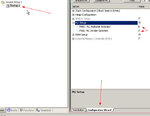
When you create a new uvision project then the default PLL settings are
LPC2138PLL.jpg

The core frequency is calculated using the following equation (refer to section 4.8.9 PLL frequency calculation in the LPC213x user manual)

FOSC the frequency from the crystal oscillator/external oscillator
CCLK the PLL output frequency (also the processor clock frequency)
M PLL Multiplier value from the MSEL bits in the PLLCFG register

CCLK = M × FOSC

MSEL=5 and the crystal is 12MHz so CCLK = 5 * 12MHz =60MHz
 
When you create a new uvision project then the default PLL settings are
View attachment 85199

The core frequency is calculated using the following equation (refer to section 4.8.9 PLL frequency calculation in the LPC213x user manual)


MSEL=5 and the crystal is 12MHz so CCLK = 5 * 12MHz =60MHz

Ya just now i checked it. i will make change in that.

Let me disable the PLL in startup.s if so any changes in code is necessary ?
 

Why do you want to run the mcu at a low frequency?
A faster clock will execute the code faster and the timers can be set accordingly.

- - - Updated - - -

Actually I have never disabled the PLL so you have to check the datasheet.
 

Why do you want to run the mcu at a low frequency?
A faster clock will execute the code faster and the timers can be set accordingly.

- - - Updated - - -

Actually I have never disabled the PLL so you have to check the datasheet.

I did Disabling the PLL didn't make any change in the expected output.

- - - Updated - - -

Why do you want to run the mcu at a low frequency?
A faster clock will execute the code faster and the timers can be set accordingly.

- - - Updated - - -

Actually I have never disabled the PLL so you have to check the datasheet.

I did Disabling the PLL didn't make any change in the expected output. The mcu produces the same output as before. Its really bit confusing
 

I have tried with a timer toggling the output at 1KHz with the PLL on (60MHz, 1/4 PCLK), when I turned if off I git 1/5 of the frequency (200Hz)

Use this code and measure the frequency in P0.22
Code:
#include <LPC213x.h>


int main(void)
{
/*
   
    P0.22:  MAT0.0 (Match output for Timer 0 channel 0)
  
*/


    PINSEL0 = 0x00000000;     /* binary: 00000000_00000000_00000000_00000000 */
    IO0DIR = 0x80000000;     /* binary: 10000000_00000000_00000000_00000000 */
    PINSEL1 = 0x00003000;     /* binary: 00000000_00000000_00110000_00000000 */
    PINSEL2 = 0x00000000;     /* binary: 00000000_00000000_00000000_00000000 */
    IO1DIR = 0x00000000;     /* binary: 00000000_00000000_00000000_00000000 */

/******************************************************************************
                             Timer0 (32bit)
*******************************************************************************
   Counter Enabled,    Counter Reset=0
   Timer mode: count on rising edge of PCLK
   Counter clk: 4 KHz, Counts every: 250 us  (calculated with peripheral clock: 15MHz)
   MCR0.0 : reset, on compare match
   MAT0.0 : On compare match Toggle bit/output
*/

    PCONP = (PCONP & 0x001817BE) | (1UL<<1);    /* Enable peripheral clock for Timer0 (default is enabled) */

    T0CTCR = 0x00;     /* binary: 00000000 */
    T0TC = 0x00000000;     /* decimal 0 */
    T0PR = 0x00000EA5;     /* decimal 3749 */
    T0MCR = 0x0002;     /* binary: 00000000_00000010 */
    T0MR0 = 0x00000001;     /* decimal 1 */
    T0MR1 = 0x00000000;     /* decimal 0 */
    T0MR2 = 0x00000000;     /* decimal 0 */
    T0MR3 = 0x00000000;     /* decimal 0 */
    T0CCR = 0x0000;     /* binary: 00000000_00000000 */
    T0EMR = 0x0031;     /* binary: 00000000_00110001 */
    T0TCR = 0x01;     /* binary: 00000001 */

   while(1)
  {
  
  
   }

}
 

Status
Not open for further replies.

Part and Inventory Search

Welcome to EDABoard.com

Sponsor

Back
Top