Continue to Site

Welcome to EDAboard.com

Welcome to our site! EDAboard.com is an international Electronics Discussion Forum focused on EDA software, circuits, schematics, books, theory, papers, asic, pld, 8051, DSP, Network, RF, Analog Design, PCB, Service Manuals... and a whole lot more! To participate you need to register. Registration is free. Click here to register now.

DC Current Measurement

Status
Not open for further replies.

nima_1981

Member level 3
Joined
Apr 22, 2010
Messages
61
Helped
0
Reputation
0
Reaction score
0
Trophy points
1,286
Location
Ocean Mind
Activity points
1,877
Hi ,
How i can Design a Dc clamp base on hall effect .
I want To measure dc current 0 to 2000 Ampere with .5 Ampere resolution .
i can not break wire because i went to use clamp hall effect
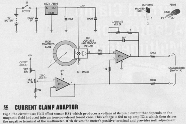
I Found this article, But i can not change this for 2000 Ampere
another , in this article does not have any specification for Iron Powerd Core ?

tahnk yiy
7121128591_1ae5e6c177_z.jpg
 
Last edited:

But i can change this for 2000 Ampere
I don't see a current range mentioned for the original schematic. Or do you have more information than shown in your post?

In fact the magnetic circuit can be calculated based on elementary magnetostatic relations and known material data.

I doubt however if the intended specification can be reliably achieved without a closed loop compensating sensor design.
 

hi , Fvm
thanks for your reply
my means is : But i can not change this for 2000 ampere
also please help me about that iron powdered core ?

this is full article

Source : **broken link removed**


CLAMP METERS are very convenient when it comes to measuring current, since they do not require breaking the current path.
Instead, they simply clip over the wire or lead that's carrying the current and the reading is then displayed on the meter.
This is not only much easier than "in-circuit" current measurements but is often a lot safer as well; eg, where high voltages and currents are
involved. However, clamp meters are not particularly useful for making low-current measurements (ie, below 1A) due to their inaccuracy and lack of resolution.
Unlike this unit, many commercial current clamp meters can only measure AC. That's because they are basically current transformers, comprising turns of wire around a magnetic core.
This magnetic core is clipped around the wire to be measured, which effectively behaves as a half-turn primary winding. The winding on the
core itself acts as the secondary and connects to the multimeter's current terminals.
The measured current is a divided down value of the true current flowing in the wire. Usually, the division ratio is 1000:1 so that 1mA shown on the meter equates to 1A through the wire that's being measured.

**broken link removed**
Clamp meters capable of measuring DC as well as AC do not use a current transformer but a Hall effect sensor instead. This sensor is placed inside a gap in an iron-powdered toroid core. It measures the magnetic flux produced as a result of the current flowing through the wire and produces a proportional output voltage.

How it works
To make it as versatile as possible, the Clamp Meter Adaptor also uses a
Hall effect censor so that it can measure bom DC and AC currents. The output of mis sensor is then processed using a couple of low-cost op amps which then provide a signal for a standard DN&l or analog multimeter.
When measuring DC current, the multimeter is set to its DC mV range and 1A through the wire in the core equates to a reading of ins V on the meter A potentiometer allows the output to be nulled (adjusted to 0 mV) when there is no current flow.
Similarly, for AC current measurements using the clamp meter, the multimeter is simply set to its ACmV range.
In this case, the DC ofisef potentiometer is not needed, since the multimeter automatically ignores any DC levels.
The high-frequency response of the adaptor for AC measurements is 3dB down ar 20kHz (ie. 0.7071 of the
real value). However, the actual measurement displayed will also depend on the high-frequency response of the multimeter itself. Some multimeters give useful readings up to 20kHz. while others begin to roll off the signal above lkHz (ie. frequencies above this will
not be accurately measured).
If necessary, the output from the Clamp Meter Adaptor can be monitored using an oscilloscope if AC measurements have to be made at
high frequencies. However. AC current measurements at 50Hz (ie. the mam frequency] will be accurate using virtually any multimeter.
Note that most multimeters are calibrated to display the RMS values of AC current measurements, although they are only accurate for
sinusoidal waveforms. This unit will not affect meter calibration, since it does not change the shape of the waveform for signals below
20kHz and only converts the current waveform to a voltage waveform. However, for non-sinusoidal waveforms, the multimeter will
display an erroneous result unless it is a true RMS type.

Demagnetising the core
One problem with clamp meters is that the core can remain magnetised after making high DC current measurement;; ie. even when the
current flow has been reduced to zero. In fact, this effect becomes apparent when measuring DC currents above about 15 OA. It is easily detected because the output from the sensor remains at several millivolt; after the current ceases flowing.
Fortunately, there's an easy solution to this. If the core does become magnetised, it can be demagnetised again by momentarily reversing the current flow in the core.
In practice, this is done by unclipping the core from the wire, replacing it over the wire upside down and applying the ourrent again for a
brief period of time.
Modified battery clamp
To keep costs down, the Clamp Meter Adaptor uses a modified car batten* clip as the current clamp This is fitted with an iron-powdered toroid core which is cut in half so mat the clip can be opened and slipped over the current-carrying wire. The Hall effect
sensor sits in a gap in the toroid. near the front of the clip - see Fig.:.
The output from this sensor is fed to a processing circuit which is built on a small PC board and housed in a
plastic case, along with the batten*.
This circuit in turn connects to the meter via two leads.
By the way. commercial clamp meters using Hall effect sensors usually place the sensor at the hinge end of the core. This can be done when the clamp material is non-magnetic. However, when the clamp is magnetic, as in this design, the magnetic flux is conducted through it instead and bypasses the airgap where the sensor sits — see Fig.:2.
This problem is solved by simply placing the sensor in an air gap at the front of the clamp, so that it cannot be bypassed.
**broken link removed**
Circuit details
Refer now to F13.I for the circuit details. It's relatively simple and comprises a dual op amp (ICla & IClb). a 3-tenninal regulator (REGl). the Hall effect sensor (HS1) and a few resistors and capacitors.
Power for the circuit is derived from a OV batten* and is fed to REGl which provides a regulated +5V rail.
This then powers the Hall effect sensor and op amps ICla Se IClb. Note that a regulated supply is necessary, since the Hall sensor output uill vary with supply rail variations.
In operation, the Hall effect sensor produces a voltage at its pin 3 output that depends on the magnetic field in the core. If the marked face of the sensor faces a south magnetic field, its output voltage will rise. Conversely, if it faces a north field, the output voltage will fall
The censor's output with no magnetic field applied to it will sit between 2.25V and 2.75V. depending on the sensor. This voltage remains stable, providing the supply voltage remains stable.
The output of the Hall effect sensor is fed to op amp ICla. This stage is wired as an inverting amplifier and it attenuates the signal by an amount that depends on the setting of trimpot VRl (calibrate). Note that the gain of ICla is set by the resistance between pins 1 & 2 divided by the 18kf! input resistor.
This means that if VRl is set to half-way. ICla has a gain of (2.5kohm + lkohm)/18kohm = 0.19.

In practice. VRl is adjusted so that it produces an output of lmV per amp flowing through the currem-carrying wire.
Op amp IClb and its associated circuitry compensate for the initial DC voltage at the output of the Hall effect sensor (ie. with no magnetic field applied). As shown. IClb is connected as a unity gain buffer with its output connected to its pin 6 inverting input.
The non-inverting input at pin 5 connects to a resistive divider network consisting of VR2. VRS and a 22kO resistor.
The output from IClb (pin 7) goes to the positive meter terminal and is also used to bias pin 3 of ICla via a lOkf} resistor. This bias voltage is
nominally about 2.5V(ie.0.5Vcc) and allows the output of ICla to swing up or down about this voltage, depending on the sensor input. It also effectively allows the quiescent voltage from the Hall sensor to be nulled so that we get a OY reading on the meter when no current is being measured. VR2 ie initially adjusted with VRS set to mid-range, so that the multimeter reads OV with no magnetic field ap-
plied to the Hall sensor. VRs is men adjusted during subsequent use of the clamp meter - it can van* IC lb's output by about 25mV to null out any small voltage readings.
In effect, trimpot VR2 acts as a coarse offset adjustment, while VRs allows fine adjustment to precisely zero the reading.
Looked at another way. VR2 & VRs are simply adjusted so that the voltage on pin 7 of IClb is the same as the voltage on pin 1 of IC la when there is no magnetic field applied to the Hall effect sensor - ie. the voltage between pins 1 a 7 is ov.
The outputs from both op amps are fed to the multimeter via 100O resistors. These provide short-circuit protection for the op amp outputs and also decouple the outputs from the cable capacitance.
**broken link removed**
Construction
Building the circuit is easy since all the parts are mounted on a small PC board coded 548 and measuring 75 x30mm. Begin construction by checking the PC board for any shorts between tracks and for any breaks in the cop- pei partem. Also check that the holedzec are all correct for the variolic components, particularly those for the PC-mount stereo socket and the on/off switch (Si).
Note that two of the corners on thePC board need to removed, so mat the board later clears the comer pillars inside the case. If your board is supplied with these corners intact, they can be cut away using a small hacksaw and carefully finished off using a rat-tail rile.
Fig.3 shows the assembly derails.
Install the resistors and wire link first, using Table 1 to guide you on the resistor colour codes. It's also a good idea to check the resistor values with a DMM. just to make sure. ICl can go in next, taking care to ensure that it is oriented correctly.
Thar done, install the trimpots and the capacitors, noting that the electrolytics must be oriented with the polarity shown. The trimpots are usu-
ally labelled with a code value, with 502 equivalent to 5kfi (VRl) and 503 equivalent to 50kD (VR2).
Next, install PC stakes at the two power supply inputs, the +5V terminal, the three VR3 terminal positions and the two multimeter outputs.
These can be followed with the switch and the PC-mount stereo socket.
Finally, complete the board assembly by installing potentiometer VR3 — it is mounted with its terminals soldered to the top of its PC stakes.
Position it so that the top of its mounting thread is at the same height as the top of the switch thread.
**broken link removed**
Drilling the case
The front panel artwork (Fig.8) can now be used as a template to mark out and drill the lid of the small plasticutility case that's used to house the board. You will need to drill two holes one for the switch and the other for the potentiometer.
In addition, you will have to drill a 4mm hole in one end of the case for the multimeter leads, plus a 7mm hole
in one side to accept the stereo socket.
The latter should be positioned 14mm down from the top of the case and 21mm in from the outside edge.
Note that it's always best to drill small pilot holes first and then carefully enlarge them to size using a tapered reamer.
Next, the integral side clips inside the box need to be removed using a chisel. Be sure to protect your eyes when doing this, as the plastic tends to splinter and fly out. You can then attach the front panel label and cut the holes out with a sharp knife.
The next step is to solder the battery chp leads to the supply terminals (red to positive, black to negative). That done, connect the multimeter leads to the output terminals, then feed these wires through the hole in the box and attach banana plugs to each free end.
Don't fit the board to the case lid at this stage. That step comes later, after calibration has been completed.
**broken link removed**
Clamp assembly
The clamp assembly comprises a car battery chp, the toroidal core and the
Hall effect sensor. Figs.5 & 6 show the assembly details for this unit.
The first step is to cut the core in half using a fine-toothed hacksaw blade. That done, the Hall sensor should be wired using a 60mm length
of 3-way rainbow cable which should be sheathed in heatshrink tubing (see Fig.5). The other end of this cable is
then connected to a 300mm length of 2-core shielded cable which in turn is terminated with a 3.5mm stereo plug.
As shown in Fig.6. the cable shields are joined together and connected to the earth lead of the rainbow cable.
They are also connected to the metalwork of the clip using a short length of hookup wire. Small pieces of insu lating tape should be used to prevent shorts between the wires where the cables join, after which the join should be covered using heatshrink tubing.

The next step is to glue the Hall sensor to one of the core pieces using some builders' adhesive (it can go in either way up). That done, glue asmall piece of plastic to the remaining part of the core gap to protect the Hall sensor from damage when the clamp closes.
Naturally, this piece of plastic needs to be slightly thicker than the Hall sensor to provide this protection.
The two core pieces can now be glued in position on the jaws of the battery clip, again using builders' adhesive. Make sure that the two halves are correctly aligned before the glue sets.
Once the core pieces are secure, the wiring for the Hall sensor can be glued in position and secured at the end of
the clip with a cable tie. In addition, the metal tabs on the clip should be bent over to hold the wire in place.
This must also be done on the other handle, so that the jaws of the clamp can be opened as wide as possible.
The 3.5mm stereo plug is wired as shown, with the tip and ring terminals connecting to the red and black wires respectively. If your twin shielded wire has different colours, take care to ensure that pin 1 on the Hall sensor goes to the tip connection. Pin 3 must go to the ring terminal and pin 2 is the ground and shield.

Ac It stands, the clamp can be slipped over leads up to 7mm In diameter. A larger clamp with jaws that open wider than the specified unit will
be necessary If you Intend measuring currents flowing In leads that are thicker than 7mm.
Note that the clamp adapter is not suitable for use with 240 VAC mains when the wiring is uninsulated.

Testing
The unit Is now ready for testing.
First, connect the batten* and check that there is +5V at the test point on the PC board (le, 5V between this test
point and ground). There should also be+5Von pln8ofICl.
If these measurements check OK. plug the clamp assembly Into the socket on the PC board and check the voltages again. If they are no longer correct, check component placement and the wiring to the Hall sensor.
Next, connect the output leads from the unit to the voltage Inputs on your multimeter and set the range to mV DC.
That done, set VR3 to Its mld-posltlon and adjust VR2 for a reading of OmV.
**broken link removed**
Calibration
The Current Clamp Adaptor Is calibrated using a 12V p ower supply, a 5m length of 0.5 mm enamelled copper
wire and an 1BC1 5W resistor.
First, wind 100 turns of the ECW around the core and connect It to the 12V supply via the 18C1 resistor as shown In Flg.7. The current through the wire will be 12/18 = 0.667A and, as far as the clamp meter Is concerned, this Is effectively multiplied by 100
due to the number of turns on the core,
All you have to do now Is adjust VRl for a reading of 66.7mV. And that's It the calibration Is complete!
Note that If the power supply Is not exactly 12V, you can compensate for this by calibrating to a different reading, Tust measure the supply voltage, divide the value by 18 (to get the current) and multiply by 100 to obtain the calibration number,
For example, If you are using a 13.8V supply, you will have to set VRl for a reading of 76,7mV on the meter (le, 13.8/18 x 100 = 76.7).
Once the calibration has been completed, the PC board can be attached to the case lid, It's held In place simply by slipping the lid over the switch and pot shafts and doing up the nuts.

Using the clamp meter
Note that before making a measurement, the DC Zero potentiometer must first be adjusted so the multimeter
reads OmV when there is no current flow, Note also that the core may need to be demagnetised after measuring
high DC currents, as described previously. This will be necessary when the DC Zero control no longer has sufficient range to null the reading,
When measuring relatively low currents (eg. between 100mA and 10A), Increasing the number ofturns of the current-earning
wire through the core will Improve the resolution. However, this will only be possible If the wire diameter allows the extra
turns to be fed through the core.
Note that the readout on the multimeter must be divided by the number of turns through the core to obtain the correct current reading, Note also that the accuracy of the unit will van* according to the temperature of the Hall sensor, particularly when making high
current measurements, Note that the readout on the multimeter must be divided by the number of turns through the core to obtain the
correct current reading. Note also that the accuracy of the unit will van* according to the temperature of the Hall sensor, particularly when making high current measurements,
By the way, It's a good Idea to mark the top of the clamp with an arrow to indicate the direction of positive
current flow once you have the unit working correctly. This can easily be determined by trial and error.
Finally, do not forget to switch the unit off when It is not In use, There's no power indicator LED to warn you that the unit Is on, so take care here!


Specifications
Output: 1A = 1mV for AC and DC ranges
Resolution: multimeter dependent (100mA with 0.1 mV resolution on multimeter)
Maximum DC current: 150A recommended (up to 900A if core is demagnetised afterwards)
Maximum AC current: 630A recommended
Linearity: typically better than 4% over range at 25*C
AC frequency response: -3dB at 20kHz (meter reading depends on multimeter AC response)
Current consumption: 15mA

Part List:
1 PC board, code 548,75 x30mm, available from the EPE PCB Service
1 plastic box. 82 x 54 x 30mm
1 iron powdered toroidal core. 28x 14x 11mm
1 50A car battery clip
1 3.5mm stereo PC board mount socket
1 3.5mm stereo jack plug
1 SPDT toggle switch (S1)
1 5kfi (code 502) horizontal trimpot (VR1)
1 50kn (code 503) horizontal trim pot (VR2)
1 ikfJ 16mm linear potentiometer (VR3)
1 red banana line plug
1 black banana line plug
1 9V battery clip
1 9V battery
1 potentiometer knob
1 4 x 4 x 2mm piece of soft plastic
1 300mm length of twin core shielded cable
1 60mm length ot 3-way rainbo*1 cable
1 200mm length of red heavy duty hookup wire
1 200mm length ot black heavy duty hookup wire
1 50mm length ot green heavy duty hookup wire
1 50mm length ot 4.8mm diameter heatshrink tubing
1 100mm cable tie
8 PC stakes
Semiconductors
1 LM358 dual op amp |IC1)
1 UGN3503 Hail effect sensor
1 78L05 5V regulator (REG1)
Capacitors
1 100uF 16V PC electrolytic
1 10uF 16V PC electrolytic
1 10OnF MKT polyester
1 1nF MKT polyester
Resislors <1%0.25W)
1 22k
1 1k
1 18k
2 100ohm
1 10k
Calibration parts
1 5m length of 0.5mm enamelled copper wire
1 18CI5W resistor
 

What's your question about iron-power cores? The quoted article use an essentially unknown core, so you can't refer to it's data. The permeability and saturation field strength of commercially available cores varies by a factor of about 50. A probably more relevant question is: Which cores are available to you?

I already mentioned, that I won't expect an accuracy in the intended range with a so called "direct-measuring" or "open-loop" current sensor, in contrast to a closed loop compensation sensor. Reasons among others are temperature coefficients of core and hall effect sensor characteristic, also core non-linearity. Commercial direct measuring sensors rarely achieve an accuracy (sum of linearity, offset and temperature drift error) better than 1% of measurement range - with built-in linearization and temperature compensation. You have been requesting 0.05 % resolution, a somehow vague specification. If it's meaned as measurement accuracy, it's even hard for a closed loop sensor.

Some manufacturer imformation pages explaining the discussed sensor operating principles.
 
To elaborate on what FvM says, a closed loop hall sensor is one that has a feedback winding around the core, in addition to the conductor being sensed hall sensor. The circuit has a feedback loop which drives current through the coil in order to force the hall sensor to detect zero flux. The coil current is then taken as the output signal, since it is directly proportional to the current through the main conductor. Operating things in a nulling method like this results in much better accuracy, since variations in core permeability due to temperature/nonlinearity are practically eliminated. If you actually want an accurate sensor, you will have to use such a nulling scheme.
 
  • Like
Reactions: FvM

    FvM

    Points: 2
    Helpful Answer Positive Rating
If you are measuring 2000 Amps, the conductor or bus bar will be BIG!!. So there's your first problem, to get a core that can actually encompass the conductor and open up enough to be put on it. From the article, you know the size of the old core (28 X 11 X 11 mm) and its colour (yellow). So with Google and this vague spec try and find out who made the original core and then scale it up to the size you need.
I think the mechanical design leaves a bit to be desired. Either the design is for NO air gap or it is designed for an air gap in which case the gap must be set with very high precision, because the length of the air gap will totally determine the sensitivity of the instrument. So it can be "calibrated " out, but must be able to return to exactly its previous length.
To do the above with home workshop equipment, first cut the core exactly in half. Take a sheet of 200 grade carborundum paper and glue with impact glue to a flat surface (piece of sheet glass?), rub the one core half so as to get both of the cut faces flat. Now the aim is to repeat this for the other core half BUT one face needs to be raised by the thickness of the Hall sensor, this is so there is no air gap when there the sensor in the gap. So one way is to get a strip of metal the same thickness, stick the same carborundum paper on it and rub the core with one face on this step, the other on the glass + paper.
Frank
 

Status
Not open for further replies.

Similar threads

Part and Inventory Search

Welcome to EDABoard.com

Sponsor

Back
Top