nikens
Junior Member level 2
I need to draw a circuit diagram how to connect pickup coil (2 wire tacho generator) to a 8 bit PIC microcontroler in order to read the signal.
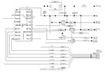
I found some schematics on the internet (attachment 1), that I don't see being correctly done. I don't understand why there is a rectifier diode and 10k resistor on the source pin of mosfet, when source should go to ground. Also don't understand why author uses 220 resistor on the gate.
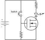
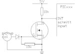
On the attachment 2 (from wikipedia) there is a simple circuit using MOSFET to switch a LED, so according to this I draw my own schematics (attachment 3), that I would like to discous if it will work to connect AC signal from pickup coil to INT pin of the PIC microcontroler (I intend to use INT interrupt).
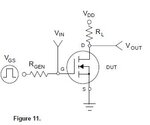
On the last attachment I posted the schematics for 2N7000 N channel MOSFET from the datasheet, that I also don't really understand. I don't see why a Rgen resistor is needed and what is the purpouse of Vin.
As far as I understand, MOSFETs work in a way where voltage on the gate open/close the barrier between drain and source. On a N channel MOSFET load is on the drain pin, source goes directly to ground. If I am not mistaken you also don't need to limit current through gate to source as there is sufficient internal resistance.
I found some schematics on the internet (attachment 1), that I don't see being correctly done. I don't understand why there is a rectifier diode and 10k resistor on the source pin of mosfet, when source should go to ground. Also don't understand why author uses 220 resistor on the gate.
On the attachment 2 (from wikipedia) there is a simple circuit using MOSFET to switch a LED, so according to this I draw my own schematics (attachment 3), that I would like to discous if it will work to connect AC signal from pickup coil to INT pin of the PIC microcontroler (I intend to use INT interrupt).
On the last attachment I posted the schematics for 2N7000 N channel MOSFET from the datasheet, that I also don't really understand. I don't see why a Rgen resistor is needed and what is the purpouse of Vin.
As far as I understand, MOSFETs work in a way where voltage on the gate open/close the barrier between drain and source. On a N channel MOSFET load is on the drain pin, source goes directly to ground. If I am not mistaken you also don't need to limit current through gate to source as there is sufficient internal resistance.
Attachments
Last edited:


