edinburghtech
Junior Member level 2
Hello
I am a wannabe Analog Designer....
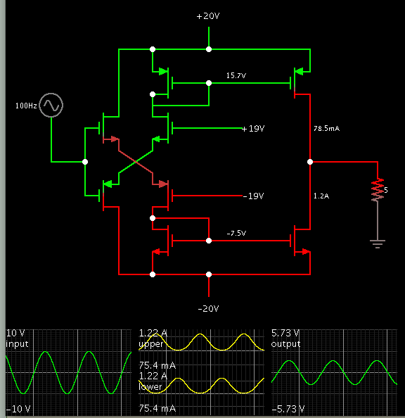
Playing around with CMOS circuits.. But not sure how to bias them. I understand MOS current equation. But not sure how to put a transistor into linear or saturation mode in a circuit (how to size the device to achieve this) . Any basic guide to biasing (DC biasing) and transistor sizing required to achieve certain mode of operation will be helpful. Also I am trying to learn a push pull amplifier configuration (figure https://obrazki.elektroda.pl/6983232400_1353596119.png). I got this circuit from https://users.ece.gatech.edu/pallen/Academic/ECE_6412/Spring_2004/L060-Push-Pull(2UP).pdf but I am not sure how to size transistors and which transistros are in what mode (Linear/Saturation). My plan is to use this circuit to drive a low impedance load (5 Ohms). Please help
Regards
Edintech
I am a wannabe Analog Designer....
Playing around with CMOS circuits.. But not sure how to bias them. I understand MOS current equation. But not sure how to put a transistor into linear or saturation mode in a circuit (how to size the device to achieve this) . Any basic guide to biasing (DC biasing) and transistor sizing required to achieve certain mode of operation will be helpful. Also I am trying to learn a push pull amplifier configuration (figure https://obrazki.elektroda.pl/6983232400_1353596119.png). I got this circuit from https://users.ece.gatech.edu/pallen/Academic/ECE_6412/Spring_2004/L060-Push-Pull(2UP).pdf but I am not sure how to size transistors and which transistros are in what mode (Linear/Saturation). My plan is to use this circuit to drive a low impedance load (5 Ohms). Please help
Regards
Edintech