robismyname
Full Member level 6
- Joined
- Jan 17, 2008
- Messages
- 390
- Helped
- 11
- Reputation
- 22
- Reaction score
- 9
- Trophy points
- 1,298
- Location
- Central Florida
- Activity points
- 4,603
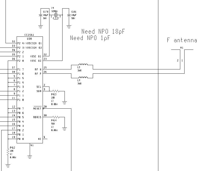
I am looking at a transceiver design. There is a differential output fed to a IFA antenna.
My questions are:
1) What is L3 and L4 doing? Are they blocking high frequencies and passing DC? Or do the inductors have something to do with the matching, if so why?
2) Suppose I wanted to do some sort of digital step attenuation. Are there any DSA's that work with differential pair antenna lines or would I have to go with a BALUN approach if I want to use the DSA?