boylesg
Advanced Member level 4
- Joined
- Jul 15, 2012
- Messages
- 1,023
- Helped
- 5
- Reputation
- 10
- Reaction score
- 6
- Trophy points
- 1,318
- Location
- Epping, Victoria, Australia
- Activity points
- 11,697
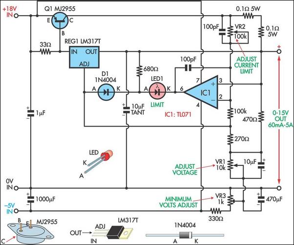
What is the purpose of the resistor labelled "see note a"?
Follow along with the video below to see how to install our site as a web app on your home screen.
Note: This feature may not be available in some browsers.
Note A tells you that the circuit must have a load of at least 30mA. If the normal load is less than this figure then that resistor should have a value which ensures it draws enough current to make up the difference between the load's current and 30mA.
e.g. if the load current was, say, 20mA, the value of the resistance should be such that it draws at least 10mA.
OK, I get it now - thanks.
I presume that below 30mA the voltage regulator has trouble regulating the voltage?
Yes, that's correct.
If the circuit which the regulator supplies draw at least 30 mA then there is no need to include this resistor.
Only if the circuit drew less than 30mA would it be necessary to include the resistor.
Not true.But BC327 is PNP and it is already in a conducting state while the LM317 is drawing a small current.
You need at least 0.7V across it to "activate" the PNP ...It is obviously got something to do with that 22R resistor but I can't quite see it.
Not true.
The PNP transistor is in non-conductive state for as long as the voltage across the 22 Ohm resistor is below 0.7V.
You need at least 0.7V across it to "activate" the PNP ...
:wink:
IanP
A = V / R
0.7 / 22 = 31mA. (it may be less than 0.7 volts)
It is 30mA current after which transistors will strat conducting. That is, the initial current is regulated by the I. Load resistor is used to avoid switching spikes and operate in linear region and not like a switching regulator.
By selecting 22 ohm resistance, it is posible to operate LM317 without a heat sink. With increased resistance, there may be a problem with stability and regulation accuracy.
Hi,
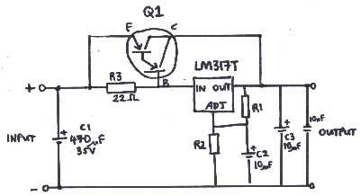
Sorry to wake an old-ish thread but I wanted to check something.
In the first schematic on the page, would the 22 ohm resistor have to be matched to whatever your current was? If you had a 15v input and the full 1.5a across the voltage regulator, would the resistor have to be rated at 22.5w or above?