Continue to Site

Welcome to EDAboard.com

Welcome to our site! EDAboard.com is an international Electronics Discussion Forum focused on EDA software, circuits, schematics, books, theory, papers, asic, pld, 8051, DSP, Network, RF, Analog Design, PCB, Service Manuals... and a whole lot more! To participate you need to register. Registration is free. Click here to register now.

[SOLVED] Can't get my circuit to work - Atmega8

Status
Not open for further replies.

avrnoob

Newbie level 3
Joined
Oct 25, 2012
Messages
3
Helped
0
Reputation
0
Reaction score
0
Trophy points
1,281
Activity points
1,303
Hi everyone,

I'm new to electronics and assembly programming. I've been struggling for the past 24 hours trying to get a simple LED to turn on (not even blink) on PB0 but seem to be doing something wrong.

First of all, my code:

Code:
sbi DDRB,0
sbi PORTB,0
loop:
rjump loop

The fuse configuration on my Atmega8 is as follows: L: 0xFF, H: 0xC9 and lock bits: 0xFF

Finally, I put together a very basic circuit after burning the code using my Genius G840 programmer and ended up writing the following:
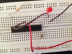
image.jpg

Supplied this with a 5v voltage source through USB but it doesn't work.

Any help in getting me started would be appreciated much!!!
 

You have to connect Vcc to pins 7, 20 and ground to 8, 22.

**broken link removed**

Alex
 
You have to connect Vcc to pins 7, 20 and ground to 8, 22.

Hi Alex,

I tried that but still does not work - connected pin 7 to 20 and 8 to 22 to pass VCC and ground.
 

In your original picture there were no power supply connections, I think I only see a ground

- - - Updated - - -

Ok, I see a positive supply and ground

- - - Updated - - -

Use this website to check or calculate your fuses
http://www.engbedded.com/fusecalc

You have set the mcu to work with an external crystal so now you need to connect a crystal and capacitors.
It would be better to leave the mcu operating with the internal RC (1,2,4 or 8MHz)
 
Sorry, ignore this rubbish:

You also have one side of the LED connected to ground, and your code is setting the pin on the other side of the LED to zero (=ground) also. So it has no potential across it.

Connect the grounded side of the LED to VCC instead of ground. Or, keep the connections as they are and change the code to set the pin to 1 to turn on the LED.
 
Last edited:

I don't think so.
I don't use ASM but I think sbi PORTB,0 sets bit0 of portB to 1

- - - Updated - - -

SBI – Set Bit in I/O Register
Description: Sets a specified bit in an I/O Register. This instruction operates on the lower 32 I/O Registers – addresses 0-31.
 

Yes, you are correct - I'll edit my post. That's what happens when I stay up all night :oops:
 

Use this website to check or calculate your fuses
https://www.engbedded.com/fusecalc

You have set the mcu to work with an external crystal so now you need to connect a crystal and capacitors.
It would be better to leave the mcu operating with the internal RC (1,2,4 or 8MHz)

Many many thanks for pointing that out. Setting my fuses (L=0xE1 and H=0xD9) fixed the problem. I was almost starting to lose my patience with this.
 

Status
Not open for further replies.

Similar threads

Part and Inventory Search

Welcome to EDABoard.com

Sponsor

Back
Top