Continue to Site

Welcome to EDAboard.com

Welcome to our site! EDAboard.com is an international Electronics Discussion Forum focused on EDA software, circuits, schematics, books, theory, papers, asic, pld, 8051, DSP, Network, RF, Analog Design, PCB, Service Manuals... and a whole lot more! To participate you need to register. Registration is free. Click here to register now.

opamp working strangely!

Status
Not open for further replies.

m2babaey

Junior Member level 2
Joined
Oct 18, 2012
Messages
21
Helped
0
Reputation
0
Reaction score
0
Trophy points
1,281
Activity points
1,445
Hi
I am trying to use an op-amp to amplify a signal. here is my schematic:
opamp.JPG

At first, Csense (positive input of the op-amp) is zero, so I am expecting the negative input to be zero
Because the gain of the op-amp is (1+2.2)/1=3.2, I am expecting the output to be zero too (0x3.2=3.2)

But the real circuit, the output is about +24V (or +21V which is near the supply voltage) and the negative input is about 6V (or about 7V)

Shouldn't the negative input be equal to positive input?
Where I am wrong?
Thanks for your help
 

I think TL072 is only intended to be used with symmetric power supply
 

I think TL072 is only intended to be used with symmetric power supply
Typical input voltage (common mode) range starts about 3V above negative supply, but TL072 doesn't show gain reversal, I think.
Your schematic also shows inverted supply voltages, which would reliably fry the device.
 

Anytime I read something like the header "opamp behaves strangely" I first look at the power supply - and very often single supply is used without knowing the consequences (proper biasing).
 

I only have one +24V supply
can I split it by 2 capacitors like below:
opamp.JPG
will the circuit work then?
Is there any other cheap solution?
Thanks again for your comments
 

The circuit will not work, because there's no DC path that centers the ground at mid supply.

You still have the OP power supply reversed, please review the data sheet.
 

From the data sheet it is clear to see that the op-amp is not rail to rail input stage and it need typically 3 Volt above Vss , for your case you are using single supply which mean that vss = 0 and then you need minimum input voltage of 3V to make the op-amp work properly. But you are providing zero input signal voltage which is out of the operation range.

- - - Updated - - -

Also you have connected the vdd to the wrong pin, you should connect it to pin 8 and the ground to pin 4.
then I dont think you will have a problem if you use single supply source
 

Apart from the link as an acknowledgment of the source it would be very useful to attach the images so that anyone reading this thread doesn't have to register in the other forum in order to see them.
 

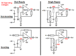
Here's the image of the single-supply op amp circuits.

I wasn't aware that you needed to join the forum to view the posts.

Op Amp Ckts.gif
 

Thanks to all!
I tried to use your last suggestion for biasing the circuit and simulated it in SPice, but again the positive input is not the same as negative input
Here it is:
opamp.JPG
Where I am wrong?
Thanks again for your help
 

Thanks to all!
I tried to use your last suggestion for biasing the circuit and simulated it in SPice, but again the positive input is not the same as negative input
Here it is:
View attachment 81844
Where I am wrong?
Thanks again for your help

Remove R21 and it will work. Be aware - the circuit can amplify ac signals only (due to the capacitive feedback).
 

Status
Not open for further replies.

Similar threads

Part and Inventory Search

Welcome to EDABoard.com

Sponsor

Back
Top