Continue to Site

Welcome to EDAboard.com

Welcome to our site! EDAboard.com is an international Electronics Discussion Forum focused on EDA software, circuits, schematics, books, theory, papers, asic, pld, 8051, DSP, Network, RF, Analog Design, PCB, Service Manuals... and a whole lot more! To participate you need to register. Registration is free. Click here to register now.

[SOLVED] interfacing AD1674 with Atmega32

Status
Not open for further replies.

ismbn

Full Member level 3
Joined
Feb 11, 2012
Messages
160
Helped
4
Reputation
8
Reaction score
4
Trophy points
1,308
Location
Mumbai. india
Activity points
2,444
Hi friend...

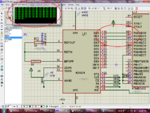
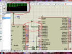
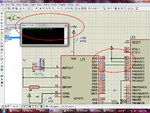
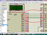
I am interfacing (in simulator) AD1674 which is a 12 bit ADC with ATmega32. I have made the connection as in the attachment. in the output of the ADC the data is changing, but when i am sending this through serial port, i am getting output as in the screenshot... it is giving output like this ascii 4080
" ≡≡≡≡...≡"

Here is the code
Code:
#include <avr/io.h>
#include <util/delay.h>

#define RC_on sbit(PORTC,5);
#define RC_off clrbit(PORTC,5);

///////////////////////////////////// Variable declarection///////////////////////////
unsigned int x=0,y=0;
unsigned long z=0;
///////////////////////////////////// End Variable declarection///////////////////////////

unsigned char read( void )
{
	/* Wait for incoming data */
	while (!(UCSRA & (1<<RXC)));
	/* Return the data */
	return UDR;
}
void print( unsigned char data )
{
	/* Wait for empty transmit buffer */
	while (!(UCSRA & (1<<UDRE)));
	/* Start transition */
	UDR = data;
}

/* Transmit String Function */
void print_str( const char *str )
{
	while (*str)
	{
		print(*str);
		str++;
	}
}
/////////////////////////////////// USART init //////////////////////////////////

void uart_init( unsigned int baud )
{
	/* Set the baud rate */
	UBRRH = (unsigned char) (baud>>8);
	UBRRL = (unsigned char) baud;
	/* Enable UART receiver and transmitter */
	UCSRB = ( ( 1 << RXEN ) | ( 1 << TXEN ) );
	/* Set frame format: 8 data 1stop */
	UCSRC = (3<<UCSZ0);
}
///////////////////////////// End of USART init /////////////////////////////////


int main(void)
{
	uart_init(103);
	DDRA=00;
	DDRB=0x00;
	DDRC=0b11111111;
	RC_on;
	while(1)
	{
		_delay_ms(1);;
		RC_off;
		x=PINA;
		y=PINB;
//		print(x);
		z=(y*255)+x;   /// when i am using z=(y*255)+x;    ≡≡ continuously
		print(z);     ///and when i am using z=(y*22)+x;       III 
		RC_on;
		
	}
}


Is this kind of response is right???
please guide me...

Ismail...
 

Attachments

  • my project 027.rar
    219.9 KB · Views: 72

My suggestion is to apply a known dc voltage in the ADC input and verify that the output value is correct (adc pins)

Then check the AVR , apply a known value to the AVR input and check if you are reading it correctly.

Then combine everything together.

You are currently feeding AC in the input of the ADC and try to read the UART output, there are many things that can be wrong in the chain.
 

Thanks for the valuable comment sir
ok i am doing this
Ismail
 

Hi...

I am not sure that what i am getting are correct output or not...

When giving +5V at the pin 20 Vin i am getting output as (D11-D0)= (1100 0000 0100);
and when -5V it is (D11-D0)= (0011 1111 1011); inverted to the +5V result,

How can i calculate what is the least value of voltage,

because if Vin = 0.005 output is (1000 0000 0001)
and Vin =-0.005 output is (0111 1111 1110)

Ismail
 

From a quick look in the datasheet the result range for bipolar mode is
0000 0000 0000 for -5,
0111 1111 1111 to 1000 0000 0000 for 0
and 1111 1111 1111 for +5
 
  • Like
Reactions: ismbn

    ismbn

    Points: 2
    Helpful Answer Positive Rating
Adc is working properly ... But Now the controller is messing...
please see the attachments
my code is
Code:
int main(void)
{
	uart_init(103);
	DDRA=0x00;
	DDRB=0x00;
	DDRC=0b11111111;
	RC_on;
	while(1)
	{
		_delay_ms(10);
		RC_off;
		x=PINA;
		print(x);
		y=PINB;
//		print(x);
		z=(y*256)+x;
//		print(z);
//		z=z>>8;
//		print(z);
		RC_on;
	}
}
 

Attachments

  • Untitled1.png
    Untitled1.png
    167.9 KB · Views: 84
  • Untitled2.png
    Untitled2.png
    168.9 KB · Views: 75
  • Untitled3.png
    Untitled3.png
    149.4 KB · Views: 65

Apply a known state to all pins, either 0 or 1 , you have several pins shown with gray color.

To combine the results use
Code:
z= (uint16_t(PINB & 0x0f)<<8) | PINA;

- - - Updated - - -

Are you sure that PA2 is constantly 0 while reading the input?
Have you tries with a direct connection to gnd?
 

Are you sure that PA2 is constantly 0 while reading the input?
Have you tries with a direct connection to gnd?

when i am connecting the direct source vcc or gnd to it shows the proper output. but when i am connecting it to the ADC output it giving trouble
see this also(attachment)...


Apply a known state to all pins, either 0 or 1 , you have several pins shown with gray color.
in start i was connecting all the pins but it giving me fist 00 and then FF FF only thats way i am not connected it that time....
ok i will connect those pin to GND...

Ismail
 

Attachments

  • Untitled4.png
    Untitled4.png
    149.5 KB · Views: 67

That seems strange, if the value is read correctly when connected to 0 or 1 then it should read correctly when you connect the ADC too.

- - - Updated - - -

Are you sure that the UART is showing data correctly?

Try a loop 0-255 and print the value to UART to check
 

sorry to late response...

i tried 0-255 loop and print it,
its printing 0 to 255

and i am using hex format to see the data because in that it prints in ascii...

ismail
 

did you check the values stores in x,y,z using a watch?
are they correct?
 

did you check the values stores in x,y,z using a watch?
are they correct?
yes i have checked it in watch window in proteus ...
1st it remains x=00,y=0,
after that when i press the step button it to directly x=255 , y=15,
ismail

- - - Updated - - -

i have changed the PORT also From PORT A to PORT B same problem...

is this error of simulation Sir?
 

can you upload the proteus project and the avr studio project
 

why not...

here it is....
 

Attachments

  • ismail.rar
    40.9 KB · Views: 42

I noticed this

Snap1.gif

and as soon as the clrbit is executed all pins go off

Snap2.gif

what is clrbit supposed to do?
I only found this
Code:
#define RC_off clrbit(PORTC,5);
 
  • Like
Reactions: ismbn

    ismbn

    Points: 2
    Helpful Answer Positive Rating
sorry i have added this in my library...

#define sbit(ADDRESS,BIT) (ADDRESS |= (1<<BIT))

#define clrbit(ADDRESS,BIT) (ADDRESS &= ~(1<<BIT))

i am using it for setting(to make 1) the bit and for resetting (to make 0)
 

In your code you set R/C to 0 which starts the conversion and disables the outputs, you read the pins while in that state and then you set it to read mode just to set it again to covert mode in the next command.
It doesn't make sense.
 
  • Like
Reactions: ismbn

    ismbn

    Points: 2
    Helpful Answer Positive Rating
Please tell me how to do the coding... for it Sir
Ismail

- - - Updated - - -

Thank you Sir I think i got it...
 

The reading must be done while the ADC is in read mode so something like

ADC convert mode
delay if needed
ADC read mode
read AVR port
 
  • Like
Reactions: ismbn

    ismbn

    Points: 2
    Helpful Answer Positive Rating
the all i have changed is
Code:
    while(1)
    {
       [B][COLOR=#ff0000] RC_on;[/COLOR][/B]
       [COLOR=#ff0000][B] _delay_us(1)[/B];[/COLOR]
        x=PINA;
        y=PINB;
        z=(y*256)+x;
        print(z);
       [B][COLOR=#ff0000] RC_off;[/COLOR][/B]
    }

i had tried this also but only the delay i was not giving so i am not getting the output...
now its working fine
Thanks For the Precious Time
Thank you so much Sir...

Ismail
 

Status
Not open for further replies.

Similar threads

Part and Inventory Search

Welcome to EDABoard.com

Sponsor

Back
Top