Continue to Site

Welcome to EDAboard.com

Welcome to our site! EDAboard.com is an international Electronics Discussion Forum focused on EDA software, circuits, schematics, books, theory, papers, asic, pld, 8051, DSP, Network, RF, Analog Design, PCB, Service Manuals... and a whole lot more! To participate you need to register. Registration is free. Click here to register now.

Some Help for ARM7 LPC2148 UART0??

Status
Not open for further replies.

xpress_embedo

Advanced Member level 4
Joined
Jul 5, 2011
Messages
1,154
Helped
161
Reputation
396
Reaction score
189
Trophy points
1,353
Location
India
Activity points
10,591
Hello!!! i just purchased a new ARM7 bases LPC2148 Development Board, it is havig on chip crystal of 12Mhz

As i don't know the Clock on which my controller is executing can any one tell me that what is the instruction cycle timing for my board and how to evaluate this.

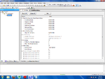
Here is my Startup.s file in Keil UVision IDE
Startup_File.png

Some one please explain me this, as i have to calculate the value of U0DLM and U0DLL

I my example program that comes with my development board, the Serial Port Initialization code is given.
which is as follow:-

Code:
void init_serial (void)  {		         /* Initialize Serial Interface       */
  PINSEL0 = PINSEL0 | 0X00000005;        /* Enable RxD0 and TxD0              */
  U0LCR = 0X83;	                         /*8 bits, no Parity, 1 Stop bit      */
  U0DLL = 0XC3;	
  U0DLM = 0X00;							 /* 9600bps baud rate */
  U0LCR = 0X03;					         /* DLAB = 0                          */
  }

I didn't get the meaning of this line
PINSEL0 = PINSEL0 | 0X00000005; /* Enable RxD0 and TxD0 */

Can any one help me regarding all this..

How to determine the clock of my board and the meaning of above line..

Thanks in advance
 

Have you tried the user manual?

Code:
FOSC: the frequency from the crystal oscillator/external oscillator
FCCO: the frequency of the PLL current controlled oscillator
CCLK: the PLL output frequency (also the processor clock frequency)
M: PLL Multiplier value from the MSEL bits in the PLLCFG register
P: PLL Divider value from the PSEL bits in the PLLCFG register

The PLL output frequency (when the PLL is both active and connected) is given by:
CCLK = M × FOSC or CCLK = FCCO / (2 × P)

The CCO frequency can be computed as:
FCCO = CCLK × 2 × P or FCCO = FOSC × M × 2 × P

The core runs @60MHz


Code:
PINSEL0 = PINSEL0 | 0X00000005; /* Enable RxD0 and TxD0 */

Again the user manual has the meaning of that (and the comment at the end of the line too):

The pin connect block allows selected pins of the microcontroller to have more than one
function. Configuration registers control the multiplexers to allow connection between the
pin and the on chip peripherals.

The code sets P0.0 to TxD operation and P0.1 to RxD

The UART clock can be calculated from
LPC_UART.png

Alex
 
Last edited:
the above line just activates the rx and tx of the controller this is done inorder not to disturb the other pins in PINSEL0.

this also can be written as PINSEL0 |= (1<<0)|(1<<2);

THIS IS BITWISE ASSIGNING OF VALUES AND THAT IS REGISTER LEVEL OF ASSIGNING VALUES
 

hi arunsharma0731,

the clock is set by right click on target& click option for target there is clock is set value. PINSEL0 = PINSEL0 | 0X00000005 in that pinsel0 is 32 bit reg. in that pinsel0.0 & pinsel0.1 is set for serial communication
 

the above line just activates the rx and tx of the controller this is done inorder not to disturb the other pins in PINSEL0.

this also can be written as PINSEL0 |= (1<<0)|(1<<2);

THIS IS BITWISE ASSIGNING OF VALUES AND THAT IS REGISTER LEVEL OF ASSIGNING VALUES


Sorry I haven't seen the User manual, actually i am newbie in arm so not able to extract the information from user manual..

PIN_Select.PNG

Thanks everyone
 

hi arun sharma,

in that we are going to use P0.0 & P0.1 as txd & rxd as serial communication. in this we can't use that port as input.
 

hi arun sharma,

in that we are going to use P0.0 & P0.1 as txd & rxd as serial communication. in this we can't use that port as input.

Yes i had done the serial communication part and its working :)
 

hi arun sharma,

is your problem solved?

Hi madhusuthanan

Yes i think.. i solved it..
Working fine in Keil, seen my data on Serial Port windows of Keil Debugger..

Will test on my hardware soon..

Thanks Guys for your help...
 

Can any one explain me the Configuration shown in these images...

I have got something but not exactly... wants to confirm myself..
Configuration-1.PNG

This is by default Startup Configuration
Under PLL Setup MSEL = 5 which means multiply Crystal Frequency by 5
and then PSEL = 2 which means divide by 2..

So if i am using a Crystal of 12MHz i will get 5*12 = 60Mhz
and then 60Mhz/2 = 30MHz

Please Tell me whether i am right or wrong..

Also tell me what is this VPBDIV Setup
VPBDIV VPB Clock = CPU_Clock/2
XCLKDIV and this is CPU Clock/4

What this means

Configuration-2.PNG
 

All this is described in the user manual so I think you should take some time to read it.

The PLL output frequency is CCLK = M × FOSC , in this case 5*12MHz=60Mhz

The PLL oscillator frequency (FCCO) must be in the range of 156MHz to 320MHz
FCCO = FOSC × M × 2 × P , in your case 12MHz * 5 * 2 * 2 = 240MHz

The APB Divider (VPBDIV) determines the relationship between the processor clock (CCLK) and clock used by peripheral devices (PCLK).
Timers, ADC, spi etc are all feed by the peripheral clock (PCLK )

The XCLK pin is avaiable only on some of the LPC2000 devices, for example lpc2294 , it doesn't exist in your mcu

Alex
 
Re: Some Help for ARM7 LPC2148 UART0 Hyperterminal??

Hi..
I have worked with UART0 and UART1 in lpc 2148. UART1 is working but i culdnt get output on hyperterminal for uART0(Since UART0 and UART1 shares the same registers regarding changes only on "U1" and "U0". Can any ne help me to solve the issue. Or any one got output in UART0?....


Regards,
Surendar
 
Last edited:

#include<lpc214x.h>
#include "timer.h"
#include "lcd.h"

char arr[15]={"SUREN UART1 "};
int i;

int main()
{
set_clock();
timer_init();
lcd_init();
PINSEL0=0x00050000;
IODIR0=0xfffdffff;

U1LCR=0x83;
U1DLL=0x86;
U1DLM=0x01;
U1LCR=0x03;
U1FCR=0x07;

while(1)
{
for(i=0;i<15;i++)
{
while(!(U1LSR&0x20));
U1THR=arr;
}
lcd_command(0x82);
display_string("UART1 Test");
lcd_command(0xC4);
display_string("Success!");
while(!(U1LSR&0x20));
U1THR=0x0D;
}
}


first i programmed for UART0... but it dint work in hyperterminal...."SUREN UART1" it should get dislayed in hyperterminal....but code not wrking for uart0.... instead i changed all the reg (eg. "U0FCR" as U1FCR) U0 as U1...it got worked and i can see the output in hyperterminal....
 

Status
Not open for further replies.

Similar threads

Part and Inventory Search

Welcome to EDABoard.com

Sponsor

Back
Top