Continue to Site

Welcome to EDAboard.com

Welcome to our site! EDAboard.com is an international Electronics Discussion Forum focused on EDA software, circuits, schematics, books, theory, papers, asic, pld, 8051, DSP, Network, RF, Analog Design, PCB, Service Manuals... and a whole lot more! To participate you need to register. Registration is free. Click here to register now.

Pic 18f4455 multiplication and division

Status
Not open for further replies.

joanaconstantina

Newbie level 6
Joined
Feb 29, 2012
Messages
11
Helped
0
Reputation
0
Reaction score
0
Trophy points
1,281
Activity points
1,380
I need help in using multiplication and division operation using PIC18F4455 in assembly language.

So, my project is like this: I have a voltage divider circuit, with the input connected to a voltage reference of 5V and the output connected to the analog input of the PIC. I used the ADC feature of PIC to obtain the 10-bit voltage output. The project aims to determine the value of an unknown resistance given the other resistance is fixed at some value.

The problem begins with the actual manipulation of the ADC output. I can't figure out a way to perform operation on a 10-bit data, divided into two registers (ADRESH:ADRESL). My pseudocode is like this:

* Get the decimal equivalent of the ADC output: Vout=(Vin/1024)*analogvalue
* Solve for Runk = Rk[(Vout/Vin)-1] where Runk is the unknown resistance and Rk is the known resistance

However, I got stuck at the first step. How do I multiply analogvalue with (Vin/1024) considering the 2 most significant bits are in another register? Anyone got an idea on this? Or better yet, is there a better way to solve for the unknown resistance, without going through this process?

Thanks in advance.
 

Multiplying or dividing by a power of 2 (such as 1024) is quite easy, for clear reasons, if you are using assembler.
Multiplying or dividing by any value other than a power of 2 involves repeated additions, or 'tricks' for certain values.
This is why, whenever someone wishes to do more than trivial math, you either need to find a pre-existing math
library in assembler, or move to C. You'd have no problem dealing with numbers larger than 8 bits in C.
I suggest you move to C, and make life easy for yourself.
 

The following routine is a 10-bit X 10-bit assembly routine written by Martin Sturm for the PIC18F series:


Code ASM - [expand]
1
2
3
4
5
6
7
8
9
10
11
12
13
14
15
16
17
18
19
20
21
22
23
24
25
26
27
28
29
30
31
32
33
34
35
36
37
38
39
40
41
42
43
44
45
46
47
48
49
50
51
52
53
54
55
56
57
58
59
60
61
62
63
64
65
66
67
68
69
70
71
72
73
74
75
76
77
78
79
80
81
82
83
84
85
86
87
88
89
90
91
92
93
94
; Multiply 10bit by 10bit unsigned
;  by Martin Sturm  2010
; Tested over full range of 10bit input combinations
;
;   a (10bit) = aH:aL   (not modified)
;   b (10bit) = bH:bL   (not modified)
;   aH:aL * bH:bL --> rH:rM:rL
;
; incorrect result if a or b has non-zero bits above the 10th
;  unless optional ANDLW 0x03 is used
;
; Algorithm
;  r = a*b
;  r = 2^16*(aH*bH) + 2^8*(aH*bL + bH*aL) + aL*bL
;             2x2           2x8     2x8      8x8
; all multiplications are unrolled
;
;  73 instructions, 57-73 cycles, 65 avg
;
 
; helper macro
mmac MACRO A,bit, uH,uL
        BTFSC   A,bit
         ADDWF  uH,F
        RRF     uH,F
        RRF     uL,F
        ENDM
 
MULT_10x10 MACRO aH,aL, bH,bL, rH,rM,rL
 LOCAL g1, g2, g3, g4
 
        ; rM:rL = aL*bL   [8x8 bit multiply] (36 cycles)
        CLRF    rM
        CLRF    rL
        CLRC
        MOVFW   bL
        mmac    aL,0, rM,rL
        mmac    aL,1, rM,rL
        mmac    aL,2, rM,rL
        mmac    aL,3, rM,rL
        mmac    aL,4, rM,rL
        mmac    aL,5, rM,rL
        mmac    aL,6, rM,rL
        mmac    aL,7, rM,rL
 
        ; rH = aH*bH   [2x2 bit multiply] (8 cycles)
        CLRF    rH
        MOVFW   bH      ; multiplicand in W
;       ANDLW   0x03    ; prevent errors if bH non-zero above 10th bit
        BTFSC   aH,1    ; carry always clear by here
         ADDWF  rH,F    ; never sets carry
        RLF     rH,F
        BTFSC   aH,0
         ADDWF  rH,F
 
        ; rH:rM += aH*bL  [2-bit x 8-bit] (7-15 cycles, avg 11)
        MOVFW   bL      ; multiplicand in W
        BTFSS   aH,0
         GOTO   g1
        ADDWF   rM,F    ; add bL
        SKPNC
         INCF   rH,F
g1
        BTFSS   aH,1
         GOTO   g2
        CLRC
        RLF     bL,W    ;  W now holds (2*bL & 0xFF)
        ADDWF   rM,F    ; add W to rM
        SKPNC
         INCF   rH,F
        BTFSC   bL,7    ;
         INCF   rH,F    ; add the upper bit of 2*bL
g2
 
        ; rH:rM += bH*aL  [2-bit x 8-bit] (7-15 cycles, avg 11)
        MOVFW   aL      ; multiplicand in W
        BTFSS   bH,0
         GOTO   g3
        ADDWF   rM,F    ; add aL
        SKPNC
         INCF   rH,F
g3
        BTFSS   bH,1
         GOTO   g4
        CLRC
        RLF     aL,W    ;  W now holds (2*aL & 0xFF)
        ADDWF   rM,F    ; add W to rM
        SKPNC
         INCF   rH,F
        BTFSC   aL,7    ;
         INCF   rH,F    ; add the upper bit of 2*aL
g4
 
        ENDM


On a side note a 10-bit ADC result represents 1024 unique values, ranging from 0 to 1023, therefore you need to divide the result by 1023, not 1024, to obtain the proper ratio.

The correct algorithm:

Vout=(Vin/1023)*analogvalue

Instead of:

Vout=(Vin/1024)*analogvalue


BigDog
 

This is why, whenever someone wishes to do more than trivial math, you either need to find a pre-existing math
library in assembler, or move to C. You'd have no problem dealing with numbers larger than 8 bits in C.
I suggest you move to C, and make life easy for yourself.

I am actually thinking of repetitive subtraction and addition for division and multiplication, respectively. However, my problem is how to account for the 2MSBs located in another register (ADRESH). It's easy dividing 8bits by 8bits using repetitive subtraction (or so I think hehe) but I'm actually dividing 10bits by 10bits to maintain precision.

By the way, as much as I would like to use C, I can't because this course is restricted to assembly language only. :((

Thanks!

- - - Updated - - -

The following routine is a 10-bit X 10-bit assembly routine written by Martin Sturm for the PIC18F series:

On a side note a 10-bit ADC result represents 1024 unique values, ranging from 0 to 1023, therefore you need to divide the result by 1023, not 1024, to obtain the proper ratio.

The correct algorithm:


Instead of:


BigDog

Thank you for the code! I will look into it, and try to insert it into my code. Oh, 1023, right! Thanks thanks. :)
 

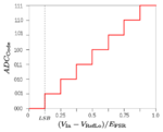
ADC_voltage_resolution.svg.png

Here is a 3-bit A/D.
There are 8 different voltage steps including zero and 1.
Its resolution is 8, not 7.

I believe Vref / 1024 is correct.
 

Here is a 3-bit A/D.
There are 8 different voltage steps including zero and 1.
Its resolution is 8, not 7.

I believe Vref / 1024 is correct.

If you examine my initial reply, it makes no counter assertions as the resolution of a 10-bit ADC and in fact I also point out there are 1024 unique values ranging from 0 to 1023.
And I should also add the choice of dividing by 1023 rather 1024 is less due to the devices resolution then the apparent choice of coding scheme and point which follows.


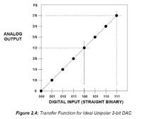
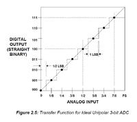
Nice graph, unfortunately in this context, it incorrectly suggests the ADC output of 0b111 represents Full Scale or Vref, which is clearly NOT the case.


The output of an ADC can be coded using one of several widely used ADC coding schemes, some are more applicable to bipolar, than unipolar ADCs.

They all have their advantages and disadvantages and the choice largely depends on the application requirements, quantization characteristics, output range, minimization of various sources of error, etc.

In this case the chosen coding scheme, which is the simplest and commonly referred to as natural or straight binary coding.

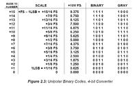
For a unipolar ADC utilizing straight binary coding, the maximum return value is not Full Scale (FS) or Vref, it is instead Vref minus the Least Significant bit (LSb).


In the case of your 3-bit ADC with a Vref = 5v, the maximum value analog value the output from the ADC can represent is 4.375v, not the 5v Full Scale of Vref.

The reason for is, of course, the largest value returned by the ADC is 0b0111 or 7, which represents a quantization uncertainty or error of 1 LSb which equates to 0.625v in this case.

The following formula/algorithm, where ADo represents the output of the ADC, has a range of 0v to Vref - LSb, or if Vref =5v, a range of 0v to 4.375v.

Ain = (Vref / 2^n) * ADo

Or in the case of 3-bit ADC:

Ain = (Vref / 8) * ADo


The following are more accurate graphics depicting the output limitations of straight binary coding:


Another example of a 4-bit ADC and the output limitations of straight binary coding in table format:


If the full scale output range of 0v to Vref is required, which is often the case in may application such as a ohmmeter then some addition software or hardware techniques must be utilized to achieve this output range. These techniques can be observed in real devices as a Tare/Clear or Calibration features. An ADC coding scheme which produces results over the full range should be beneficial in this application as it would allow a zero ohm reading to be obtained when the probes or test points are shorted, as similar results would be expected from an ohmmeter.

One of the simplest techniques to achieve full scale output is the following formula/algorithm:

Ain = (Vref / (2^n -1)) * ADo

Or in the case of 3-bit ADC:

Ain = (Vref / 7) * ADo

Or in the case of 10-bit ADC:

Ain = (Vref / 1023) * ADo


Admittedly the use of the phrase, "correct value" in my initial reply, was a poor choice as the implementation of the technique is not appropriate in all cases.


The technique does not effect the ADC device resolution, however it does have the effect of scaling the output over the entire range of 0v to Vref. The technique does slightly increase quantization uncertainty/error and introduce some small amount of scaling error, however these errors are far less than the 1% accuracy of a precision resistor.

Additional information concerning ADC/DAC coding schemes is available in the following document:

FUNDAMENTALS OF SAMPLED DATA SYSTEMS - ANALOG-DIGITAL CONVERSION


Of course there are other techniques which can be implement in either hardware or software which provides coding output over Full Scale, however most are considerably more elaborate.


On a side note, for ADC or DSP intensive applications, typically the more useful coding scheme of fractional binary coding is utilized, which is always normalized to Full Scale (FS). However, this coding scheme does require considerably more arithmetic operations of a more elaborate ADC hardware module.


I hope I've cleared any confusion as to the motive of my suggestion.

BigDog
 

Wow! Very detailed explanation. Got it! Super thanks! :)

Just a question about macros.. This will be my first time using this. In order to use your 10x10bit multiplication code, I just have to specify the destinations of the data right? So for the macro, MULT_10x10 MACRO aH,aL, bH,bL, rH,rM,rL, I have to specify 7 registers, the first four registers are my operands, and the last three will store the result. Am I on the right track? And what is the purpose of the "mmac" macro? Thanks!

Do you happen to have a code for 10x10bit division also?

Thank you so much for replying. I am finally getting a grasp on this. And I'm sorry for asking too much. :|
 

Hi guys, I got this 16x8 multiplication macro in piclist and it's just what I needed. However, I am having trouble using it since it's my first time using macros. Here's the code:

Code:
#include<P18F4455.INC>

	CONFIG	FOSC = INTOSC_EC
	CONFIG	WDT = OFF
	CONFIG	PBADEN = OFF
	CONFIG	MCLRE = ON
	CONFIG	DEBUG = ON
	CONFIG	ICPRT = ON
	CONFIG	LVP = OFF
	CONFIG	PWRT = ON

	cblock h'20'
		OP1H
		OP1L
		OP2
		RESH
		RESM
		RESL
	endc

	ORG 	0x000
	GOTO	MAIN

MAIN
; configure clock	
	MOVLW	b'01110010'		; set internal oscillator to 8MHz
	MOVWF	OSCCON			
MAIN_LOOP

	MOVLW	0x27
	MOVWF	OP1H
	MOVLW	0x10
	MOVWF	OP1L
	MOVLW	0x64
	MOVWF	OP2
	MOVLW	0x00
	MOVWF	RESH
	MOVWF	RESM
	MOVWF	RESL

	MULT_16x8_FASTEST	OP1H,OP1L, OP2, RESH,RESM,RESL

	GOTO	MAIN_LOOP

; 16bit by 8bit unsigned multiply
;  by Martin Sturm 2010
; tested
;
; aH:aL * b --> r3:r2:r1
;
; 69 instructions, 69 cycles
;

; helper macro
mmac MACRO A,bit, u2,u1
	BTFSC	A,bit
	 ADDWF	u2,F
	RRF	u2,F
	RRF	u1,F
	ENDM

MULT_16x8_FASTEST MACRO aH,aL, b, r3,r2,r1

	CLRF	r3
	CLRF	r1
	CLRC
	MOVFW	b	; comment out if 8bit multiplicand already in W
			;  also, b can be removed from macro arguments
	mmac	aL,0, r3,r1
	mmac	aL,1, r3,r1
	mmac	aL,2, r3,r1
	mmac	aL,3, r3,r1
	mmac	aL,4, r3,r1
	mmac	aL,5, r3,r1
	mmac	aL,6, r3,r1
	mmac	aL,7, r3,r1
	
	CLRF	r2
	; carry already clear from last RRF of mmac above
	; 8bit multiplicand still in W
	mmac	aH,0, r3,r2
	mmac	aH,1, r3,r2
	mmac	aH,2, r3,r2
	mmac	aH,3, r3,r2
	mmac	aH,4, r3,r2
	mmac	aH,5, r3,r2
	mmac	aH,6, r3,r2
	mmac	aH,7, r3,r2

	ENDM

END

Heeeelp! Everytime I build it, an error occurs at the line where I call the macro. Is there something wrong in the "call" line? Or did I misplace the macro? Do macros need to be defined first? Heeeeelp! :(

Right now, I want to know if the code actually works so I can incorporate it in my code. Help, anyone? :(
 

Status
Not open for further replies.

Part and Inventory Search

Welcome to EDABoard.com

Sponsor

Back
Top