Continue to Site

Welcome to EDAboard.com

Welcome to our site! EDAboard.com is an international Electronics Discussion Forum focused on EDA software, circuits, schematics, books, theory, papers, asic, pld, 8051, DSP, Network, RF, Analog Design, PCB, Service Manuals... and a whole lot more! To participate you need to register. Registration is free. Click here to register now.

Measuring sine wave of 220v with pic

Status
Not open for further replies.

flower2007

Newbie level 6
Joined
Jul 19, 2007
Messages
12
Helped
2
Reputation
4
Reaction score
2
Trophy points
1,283
Activity points
1,362
I want to measure sine wave of 220v with pic microcontroller using simple resistive network.
i will provide 2.5 volts offset, so that the voltage changes at the input of adc represents both negative and positive half cycles.

the only thing that i m confused about is how to start sampling and when to stop it.
and also how do i know how many samples recorded in that duration.
 

It's up to you to decide when to start and stop sampling. The number of samples recorded is a function of the sampling time and sample rate, right?

What information are you trying to extract from your input? Frequency? Amplitude? Digitizing accurate of copy input?
 

Do you want to measure amplitude only? Then you could use a peak detector. Then you need not take so many samples per cycle.

Or do you want to measure frequency? Then you should measure time between every other zero crossing. This will involve creating a flag variable or two, and noticing when signal goes above or below a certain value.


I want to calculate the True RMS voltage from those samples.
What i have in my mind to use two pins of pic microcontroller, one for ADC input and other for zero crossing detector.
when ever zero crossing occur the ADC should start sampling and continue till the zero crossing occur again.
Is it ok?. and is there any other simple and accurate method?

- - - Updated - - -

It's up to you to decide when to start and stop sampling. The number of samples recorded is a function of the sampling time and sample rate, right?

What information are you trying to extract from your input? Frequency? Amplitude? Digitizing accurate of copy input?

I want to calculate the True RMS voltage from those samples.
 

You are on the right track.

Try different sampling rates. The aim is to sample as frequently as possible, so you can catch all spikes and dips in the waveform.

Remember you're taking a chance when you connect mains AC through a resistive divider to your microcontroller.

Perhaps you already plan to split the large resistance in two, and install a resistor in each incoming leg? So there is no direct connection to mains?
 

I wouldn't bother with the zero crossing input, let the software determine the zerocrossing (software is free, hardware costs money, board space and reliability). If you know the maximum input frequency and the maximum allowable error, you can determine your minimum sample rate. Then all you have to do is have a sampling window longer than your maximum input period (to ensure you get two zero-crossings).
 
You are on the right track.

Try different sampling rates. The aim is to sample as frequently as possible, so you can catch all spikes and dips in the waveform.

Remember you're taking a chance when you connect mains AC through a resistive divider to your microcontroller.

Perhaps you already plan to split the large resistance in two, and install a resistor in each incoming leg? So there is no direct connection to mains?

Yes i have divided resistor in 4. two resistors in each leg. actually i have used a passive low pass filter which filters input of the adc as well as provide resistance to the mains.

- - - Updated - - -

I wouldn't bother with the zero crossing input, let the software determine the zerocrossing (software is free, hardware costs money, board space and reliability). If you know the maximum input frequency and the maximum allowable error, you can determine your minimum sample rate. Then all you have to do is have a sampling window longer than your maximum input period (to ensure you get two zero-crossings).

It looks very interesting.can u help me a bit more , how the software can determine zero crossing with out hardware.
many thanks.
 
All the software has to do is look at the polarity of the input samples. When two successive samples have different signs, you've crossed zero. You have to determine what resolution you need for your particular application.
 
All the software has to do is look at the polarity of the input samples. When two successive samples have different signs, you've crossed zero. You have to determine what resolution you need for your particular application.

Sory I m still not getting you. we cant measure -negative voltages with adc. How the sign will change as there are always positive voltages at the input of adc. >>> Do u mean when the voltages are less than 2.5 volts are considered as negative voltage.
Initially I m going to take 20 samples for one complete cycle. Once the system starts working then I can play for accuracy.

thank you.
 

Do u mean when the voltages are less than 2.5 volts are considered as negative voltage.

Yes, that's the way to do it, because you stated you will add a 2.5V offset.

It may be tricky to lift the AC waveform to exactly 2.5V. Consider monitoring the positive and negative peaks every so often, and calculating the halfway point between them as the zero line.
 
Yes, that's the way to do it, because you stated you will add a 2.5V offset.

It may be tricky to lift the AC waveform to exactly 2.5V. Consider monitoring the positive and negative peaks every so often, and calculating the halfway point between them as the zero line.

I will do it now , and hopefully will get positive results.
Barry and BradtheRad , thank you very much for your great help.
 
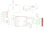
Look this project :

TrueRMS-imagecheck1.png

Code:
/*
Project Name: TrueRMS Voltmeter
RMS measuring Voltmeter not limited to low frequency,
low distortion sine waves.
Configuration:
MicroController: PIC18F4550
Oscillator: HS, 48.0000 MHz
Author: Ceramic Resonator
Daniel Johnson
California State University, Fullerton
Graduate Student, December 2009
johnson.danielb@yahoo.com
*/
#define TRUE 1
#define FALSE 0
#define r200mv 1*0.25
#define r2v 10*0.00322
#define r20v 100*0.00144
#define r200v 1000*0.000985
// Lcd pinout settings
sbit LCD_RS at RC6_bit;
sbit LCD_EN at RC4_bit;
sbit LCD_D7 at RD0_bit;
sbit LCD_D6 at RD1_bit;
sbit LCD_D5 at RD2_bit;
sbit LCD_D4 at RD3_bit;
// Pin direction
sbit LCD_RS_Direction at TRISC6_bit;
sbit LCD_EN_Direction at TRISC6_bit;
sbit LCD_D7_Direction at TRISD0_bit;
sbit LCD_D6_Direction at TRISD1_bit;
sbit LCD_D5_Direction at TRISD2_bit;
sbit LCD_D4_Direction at TRISD3_bit;
// Structures

// Shared Variables
unsigned long range;
long AvgV , DC_offset;
long RMS_Plus_DCoffset;
unsigned long RMS_value;
unsigned long CrestFactor;
unsigned long Vread_sqrd;
void setup_IO()
{
// Interupt settings
// RCON.IPEN = 1; // Enable Interupt High/Low feature
// IPR1.RCIP = 0; // USART Rx set_Low
// INTCON.GIEH = 1; // Enable Global Interupts
// INTCON.GIEL = 1; // Enable Global Peripheral Interupts
// PIE1.RCIE = 1; // Enable Usart_Rx Interupt
// Disable USB!!!
UCON = 0x00;
UCFG = 0x08;
// A/D
ADCON1 = 0x1B; // Set A/D pins 0,1,2,Vref+ Enabled
TRISA = 0x0F; // PORTA.RD0-RD3 is input
// 20x LCD
TRISC = 0;
TRISD = 0;
Lcd_Init();
Lcd_Cmd(_Lcd_CLEAR); // Clear display
Lcd_Cmd(_Lcd_CURSOR_OFF); // Turn cursor off
// Initialize delay
Delay_ms(35);
}
void update_display()
{
char disp_DC[5];
char disp_RMSDC[5];
char disp_RMS[5];
char disp_CF[3];
DC_offset = range * DC_offset;

FloatToStr(DC_offset, disp_DC);
RMS_Plus_DCoffset = range * RMS_Plus_DCoffset;
FloatToStr(RMS_Plus_DCoffset, disp_RMSDC);
RMS_value = range * RMS_value;
FloatToStr(RMS_value, disp_RMS);
CrestFactor = range * CrestFactor;
FloatToStr(CrestFactor, disp_CF);
Lcd_Cmd(_Lcd_CLEAR); // Clear display
Lcd_Out(1, 1, "DC:");
Lcd_Out(1, 5, disp_DC);
Lcd_Out(1, 11, "RMS:");
Lcd_Out(1, 15, disp_RMS);
Lcd_Out(2, 1, "DC+RMS:");
Lcd_Out(2, 9, disp_RMSDC);
Lcd_Out(2, 13, "CF:");
Lcd_Out(2, 17, disp_CF);
}
void find_range()
{
unsigned int range_check;
range_check = adc_read(RA1); // Range Lower Upper
if ( 767 < range ) // 0.2 768 1023
range = r200mv;
if ( 511 < range < 768 ) // 2 512 767
range = r2v;
if ( 255 < range < 510 ) // 20 256 511
range = r20v;
if ( range < 254 ) // 200 0 255
range = r200v;
}
void sample_and_compute() // VRMS = [ Avg(v^2) ] ^1/2
{
long Vread;
unsigned long Vpeak = 0;
unsigned long Vtotal = 0;
unsigned int s = 0;

for ( s = 0 ; s < 7000; s++ )
{
Vread = adc_read(RA0);
if(Vread > 512){
Vread = Vread-512; }
else if(Vread < 512) {
Vread = -1*(512-Vread); }
if (fabs(Vread) > Vpeak) {
Vpeak = fabs(Vread); }
Vread= Vread*0.004883;
Vread_sqrd = Vread * Vread;
Vtotal = Vread_sqrd+Vtotal;
}
AvgV = Vtotal/7000;
DC_offset = AvgV-3.23;
RMS_Plus_DCoffset= sqrt(AvgV);
RMS_value = RMS_Plus_DCoffset - DC_offset;
CrestFactor = Vpeak/RMS_Value;
}
void main()
{
setup_IO(); // Initializations
while(TRUE)
{
sample_and_compute();
update_display();
}
}
 

Attachments

  • Daniel-Johnson-A2D-TrueRMS-Voltmeter.pdf
    1.1 MB · Views: 216
Status
Not open for further replies.

Similar threads

Part and Inventory Search

Welcome to EDABoard.com

Sponsor

Back
Top