Continue to Site

Welcome to EDAboard.com

Welcome to our site! EDAboard.com is an international Electronics Discussion Forum focused on EDA software, circuits, schematics, books, theory, papers, asic, pld, 8051, DSP, Network, RF, Analog Design, PCB, Service Manuals... and a whole lot more! To participate you need to register. Registration is free. Click here to register now.

Resetting Fuse Bits in ATMEGA328 Microcontroller

Status
Not open for further replies.

Bish00

Newbie level 4
Joined
Jul 25, 2012
Messages
7
Helped
0
Reputation
0
Reaction score
0
Trophy points
1,281
Activity points
1,339
Hi,

I'm new to this forum but I have been following it for a while and received good advices :). Now I need help, since I think I messed up fuse bits :D. So here's my problem:

I have ATMEGA328-PU microcontroller and I use WinAVR and AVRDude to change fuse bits. Before I did fuse bits change, the default values were following: lfuse: 0x62, hfuse: 0xd9, efuse:0xff. What I did was that I changed fuse bits to following settings: lfuse: 0x60, hfuse: 0xd9, efuse:0xff. Now I get famous error "initialization failed rc=-1". I use usbtiny and I have tried to find solution for this problem from ladyada.net but no solutions. They tell there that just check your connections, well I have tried to check and they are correct.

Then I used other microcontroller but exactly the same model and reading fuse bits and everything else is working. However I didn't to try to write fuse bits with this new microcontroller, but the thing is that it worked and that other didn't worked. Then I saw in this forum solution where I have to put oscillator of 4 Mhz, not crystal oscillator, erase the chip and reprogram fuse bits. This didn't help either. Any solution for this?
 

You can use this calculator https://www.engbedded.com/fusecalc

You have currently set your mcu to external clock so you need to connect an external clock source in the XTAL1 pin to reprogram it.
You can use another avr set to toggle a pin on/off as a clock or a crystal oscillator or even a 555 should do.

- - - Updated - - -

Consider using AVR burn-o-mat front end in the future to avoid similar mistakes in the fuse settings
http://avr8-burn-o-mat.aaabbb.de/
 

I can't even reprogram it because I get "initialization failed rc=-1" error. This chip must be somehow erased and there's a way. Does AVR burn-o-mat front end supports atmega328P?
 

You chip expects an external clock source, unless you provide it it is completely dead so it can't communicate or be reprogrammed.
Connect an external clock source and it will work fine and you will be able to reprogram it.

The simplest thing you can do is use a pin of the working AVR

Code:
int main(void){
DDRC|= (1<<5); // set PC5 as output

while(1){
PORTC ^= (1<<5); // toggle the pin

}
}

Now connect that pin to XTAL1 of the other avr with the wrong fuse settings

I just want to make sure that is this external clock source **broken link removed**, I use that particualr oscillator for XTAL1. Is it proper part or no?
 

Yes this is an external oscillator and will work fine but I don't think there is a reason for you to spend so much , just use another avr or even a 555 oscillator
 

Yes this is an external oscillator and will work fine but I don't think there is a reason for you to spend so much , just use another avr or even a 555 oscillator

I tried to run that program, but still same problem. I think the chip might be dead. :(
 

I connected that particular oscillator to XTAL1 (PIN 1), GND to GND, PWR to PWR and one pin was not connected.
 

Did you check if your oscillator gives output?
You should measure about 2.5v DC in the XTAL1 pin.

- - - Updated - - -

What is the frequency of the oscillator you have used?
 

Did you check if your oscillator gives output?
You should measure about 2.5v DC in the XTAL1 pin.

- - - Updated - - -

What is the frequency of the oscillator you have used?

Yes I tested my oscillator and it works. I connected it properly and for clock signal I connected to resistor of 200Ohm and from that to LED and it lighten up very fine, so oscillator works. I think the chip is dead, because when I did fuse bits reprogramming it asked me some question that do you want to return settings or no or something like that and I answered yes, and it took so long time and nothing happened so I closed cmd and I think I screwd up with that thing. Maybe that was the thing that caused to chip to work inappropriate or doesn't get connection.
 

There is no way to kill the chip unless you provide voltages higher than the specs.

What is the frequency of your crystal oscillator?
Which programmer hardware do you have?
 

There is no way to kill the chip unless you provide voltages higher than the specs.

What is the frequency of your crystal oscillator?
Which programmer hardware do you have?

The cyrstal oscillator uses 1.0 Mhz and programmer hardware I use is USBTiny.
 

Hi, I can use this technique with my ATMEGA 2560?

Thanks.
 

In you mean applying an external clock to XTAL1 then yes.
 

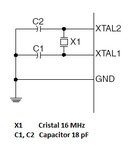
Thanks, I use this diagram?

Sorry for my english.

Thanks.

Averia Mega.jpg
 

Yes , that is correct when you have set the clock to use an external crystal.
If you set the fuses to a wrong setting then disconnect the crystal and the capacitors and connect an external clock to XTAL1 in order to reprogram the fuses of the mcu to a correct value.
 

Status
Not open for further replies.

Similar threads

Part and Inventory Search

Welcome to EDABoard.com

Sponsor

Back
Top