Continue to Site

Welcome to EDAboard.com

Welcome to our site! EDAboard.com is an international Electronics Discussion Forum focused on EDA software, circuits, schematics, books, theory, papers, asic, pld, 8051, DSP, Network, RF, Analog Design, PCB, Service Manuals... and a whole lot more! To participate you need to register. Registration is free. Click here to register now.

Changing current circuit in oscillator buffer

Status
Not open for further replies.

neazoi

Advanced Member level 6
Joined
Jan 5, 2008
Messages
4,123
Helped
13
Reputation
26
Reaction score
15
Trophy points
1,318
Location
Greece
Activity points
36,955
Hello,
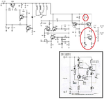
The oscillator design attached uses a simple bc547 and a LED (red circles) as a contant current source for the buffer amplifier FET (am I right?)

Could I use the constant current source circuit shown inside the square to replace the current source? The circuit is described here **broken link removed**

How should I connect this to the FET?

Or should I use a more straight forward circuit like this **broken link removed**
 

Attachments

  • oscillator_small.png
    oscillator_small.png
    358.1 KB · Views: 142

The bias topology of the last source follower FET is a "hybrid, Constant-Current / Self-Biasing" technique, which was implemented to establish a flat load line without sacrificing the dynamic range.
Perhaps can add a different current source than the one is working now, but would be a challenge to tune the bias point to maintain a good sinusoidal signal at the output. If you look to the schematic all the transistors in the circuit (BJTs and FETs are DC coupled one to each other), including the last FET source follower, which I mentioned is using hybrid bias.

On the other hand there is a mistake at the modulation input. There should be AM not FM, as modulation input. At that point, the oscillator can only be AM modulated, and not FM.
 
  • Like
Reactions: neazoi

    neazoi

    Points: 2
    Helpful Answer Positive Rating
The bias topology of the last source follower FET is a "hybrid, Constant-Current / Self-Biasing" technique, which was implemented to establish a flat load line without sacrificing the dynamic range.
Perhaps can add a different current source than the one is working now, but would be a challenge to tune the bias point to maintain a good sinusoidal signal at the output. If you look to the schematic all the transistors in the circuit (BJTs and FETs are DC coupled one to each other), including the last FET source follower, which I mentioned is using hybrid bias.

On the other hand there is a mistake at the modulation input. There should be AM not FM, as modulation input. At that point, the oscillator can only be AM modulated, and not FM.

Yesterday I tried the several options.
The LED circuit was actually using a 39R instead of the 33R shown on the schematic, the current was at 16.92mA and the voltage at the base of the transistor was 1.43v.
I modified the bias like this **broken link removed**. The modified transistor circuit, uses now a 22R (not a 33R), the current is 16.81mA but the voltage at the base of the transistor is now 1.14v.
Do you think this lower voltage causes any problem?
Nevertheless, the output waveform was the same in amplitude and any distortions on both cases.
I thought this current source affects only the final FET.

About the FM, the original schematic did not mention FM input but MOD input. I conducted that is was an FM modulation after feeding an audio tone and seeing the signal on the spectrum analyzer. At a constant tone volume and frequency, it shifts the carrier backwards and forwards. When I change the tone volume (amplitude) it shifts the carrier more. So I think this is FM?

To be honest I was surprized, as I thought it should be AM not FM as well.
 

I put the circuit in a simple Spice simulator and there is no difference using the original bias or the second one. You may use the new one or keep the old one, there is no difference (and almost the same quiescent current on the FET).
In any oscillator if is directly AM modulated, inherently it will appear a parasitic FM component. For better checking, instead of a spectrum analyzer, use an oscilloscope and see the RF output waveform, for different modulation levels.
 
  • Like
Reactions: neazoi

    neazoi

    Points: 2
    Helpful Answer Positive Rating
I put the circuit in a simple Spice simulator and there is no difference using the original bias or the second one. You may use the new one or keep the old one, there is no difference (and almost the same quiescent current on the FET).
In any oscillator if is directly AM modulated, inherently it will appear a parasitic FM component. For better checking, instead of a spectrum analyzer, use an oscilloscope and see the RF output waveform, for different modulation levels.

Thank you very much, for both the simulation and the hints. I will do so.
 

Status
Not open for further replies.

Part and Inventory Search

Welcome to EDABoard.com

Sponsor

Back
Top