Continue to Site

Welcome to EDAboard.com

Welcome to our site! EDAboard.com is an international Electronics Discussion Forum focused on EDA software, circuits, schematics, books, theory, papers, asic, pld, 8051, DSP, Network, RF, Analog Design, PCB, Service Manuals... and a whole lot more! To participate you need to register. Registration is free. Click here to register now.

Auxiliary supply for dc to dc converter

Status
Not open for further replies.

wei9321

Member level 3
Joined
Feb 5, 2009
Messages
55
Helped
0
Reputation
0
Reaction score
0
Trophy points
1,286
Activity points
1,609
what condition is necessary for adding Auxiliary supply winding to the dc to dc converter of transformer ?
thanks !
 
Last edited:

Usually the Auxiliary supply is added for off-line converters, in order to provide power for the dc-to-dc control IC. It is generally needed when creating a lower, isolated voltage from a higher voltage. It increases efficiency (the control IC draws its power from a stepped-down voltage) and improves reliability (the alternative, using a resistor from the input voltage to supply the capacitor, might not provide enough current at peak demand).

Hope this helps.
 
Helllo,

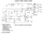
I am trying to put the UC3845 working without being mounted on a full circuit configuration. I've a doubt here regarding that dc-to-dc control IC. Please, see the figure below (taken from the datasheet from ON Semiconductor):

1.JPG

That auxiliary bobbin in the primary side is used instead of using the optcoupler to sample from the secondary side?

Can someone tell how can I simulate that without having the full circuit mounted? (I am using a breadboard) Is it sufficient to put 2.5V on that pin? Since the other pin of the Error Amplifier is 2.5V. BTW, if this was in a circuit, like the figure above, we should select the pair of resistor in order to put 2.5V in that pin? Is that it?

Best regards.
 

dear ZekeR:
can you give an example for this paragraph"It is generally needed when creating a lower, isolated voltage from a higher voltage."?
thanks !

Usually the Auxiliary supply is added for off-line converters, in order to provide power for the dc-to-dc control IC. It is generally needed when creating a lower, isolated voltage from a higher voltage. It increases efficiency (the control IC draws its power from a stepped-down voltage) and improves reliability (the alternative, using a resistor from the input voltage to supply the capacitor, might not provide enough current at peak demand).

Hope this helps.
 

This is often done simply for efficiency's sake. To boot
and run the PWM controller you need (say) 100mA.
This would come from the input supply, and at 40V in
you'd be talking 4W draw with most of it dumped in a
limiting resistor. That's 4% off the top in a 100W brick.

Now if you either-ORed the feed with a winding derived
10V source, that same 100mA is 1W and only a 1%
inefficiency term. Given how hard you struggle to squeeze
percentage points out of the powertrain, getting 3%
back for a few turns of wire and a cheap diode or two
is a bargain.
 

Status
Not open for further replies.

Similar threads

Part and Inventory Search

Welcome to EDABoard.com

Sponsor

Back
Top