Continue to Site

Welcome to EDAboard.com

Welcome to our site! EDAboard.com is an international Electronics Discussion Forum focused on EDA software, circuits, schematics, books, theory, papers, asic, pld, 8051, DSP, Network, RF, Analog Design, PCB, Service Manuals... and a whole lot more! To participate you need to register. Registration is free. Click here to register now.

Please help me on the pulse transformer waveform spike problem

Status
Not open for further replies.

vampire_sir

Newbie level 3
Joined
Mar 16, 2011
Messages
3
Helped
0
Reputation
0
Reaction score
0
Trophy points
1,281
Activity points
1,321
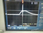
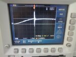
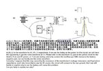
Please refer to the picture below, A2, B2 and C2 are the waveform for A1, B1 and C1 respectively; if I use the battery as the power supply for this circuit, we will have the chance to get a spike on the output waveform as C2 at the circuit position C1. Please refer to the waveform C2, part in the yellow circle for the details. If I use a DC power supply, or even I use the battery power supply, but connect the oscilloscope GND clamps to the battery negative part, I can then get the spike to be removed.

Currently, I suppose that this may be caused by the resonance of the transformer's leakage inductance and Equivalent capacitance, and I also know that to use this DC power supply, the circuit will connect to the real ground through the DC power supply. But I still can't explain why to use the battery power supply will cause this problem.

I am really appreciated if you can help to make me clear on this.
100-311 arcing help.JPG

Below are the real C2 waveform

13372350024fb4963aa9b78_small.jpg

13372349934fb49631a41a6_small.jpg
 

Dear vampire_sir
Hi
I think your circuit is a flyback converter , and here are my statements :
1- the out put load shouldn't be high . a flyback converter with high loads , can be pretty dangerous .
2- you don't have any capacitor in out put ( and of course any diode )
3- do you have current and voltage feedback ? ( fly back converter would be better to works in current mode , situation .)
4- you forgot to mention exact parameters of your circuit e.g frequency of operation or inductance of your transformer ... etc .
Best Wishes
Goldsmith
 

Please refer to the picture below, A2, B2 and C2 are the waveform for A1, B1 and C1 respectively; if I use the battery as the power supply for this circuit, we will have the chance to get a spike on the output waveform as C2 at the circuit position C1. Please refer to the waveform C2, part in the yellow circle for the details. If I use a DC power supply, or even I use the battery power supply, but connect the oscilloscope GND clamps to the battery negative part, I can then get the spike to be removed.
Wait, so you mean that you're changing where the oscilloscope ground is connected? Well it's not surprising for that to cause a different waveform to appear on the oscilloscope, though it probably doesn't have to do with any change in capacitance from the oscilloscope.

What do you actually want the circuit to do? It seems like a great circuit for burning transistors or generating dangerously high voltages.
 

Dear vampire_sir
Hi
I think your circuit is a flyback converter , and here are my statements :
1- the out put load shouldn't be high . a flyback converter with high loads , can be pretty dangerous .
2- you don't have any capacitor in out put ( and of course any diode )
3- do you have current and voltage feedback ? ( fly back converter would be better to works in current mode , situation .)
4- you forgot to mention exact parameters of your circuit e.g frequency of operation or inductance of your transformer ... etc .
Best Wishes
Goldsmith

Hi, Goldsmith, thanks for your help, I list my answers below:
1, the 1Mohm resistor is intented to design as it was; this output waveform is a pulse with 6KV amplitude;
2, Yes, I don't have any capacitor in the output or any diode
3, No, I don't have current and voltage feed back;
4, The drive pulse, A2, has the 150uS width, and 4.5V amplitude; and the frequency for this drive pulse is 100Hz;
The transformer related information:
Output energy: 270~400uJ
Primary L=175~300uH
primary resistor: 0.24~0.39 ohm
Secondary resistor: 1200~1900 ohm

- - - Updated - - -

Wait, so you mean that you're changing where the oscilloscope ground is connected? Well it's not surprising for that to cause a different waveform to appear on the oscilloscope, though it probably doesn't have to do with any change in capacitance from the oscilloscope.

What do you actually want the circuit to do? It seems like a great circuit for burning transistors or generating dangerously high voltages.

Hi, Mtwieg, thanks for the feed back; this circuit was intend to generate a high voltage pulse with limited energy; Since you think that it was not suprising to for that to cause a different waveform to appear on the oscilloscope, can you explain a little bit more?
 

Status
Not open for further replies.

Similar threads

Part and Inventory Search

Welcome to EDABoard.com

Sponsor

Back
Top