Continue to Site

Welcome to EDAboard.com

Welcome to our site! EDAboard.com is an international Electronics Discussion Forum focused on EDA software, circuits, schematics, books, theory, papers, asic, pld, 8051, DSP, Network, RF, Analog Design, PCB, Service Manuals... and a whole lot more! To participate you need to register. Registration is free. Click here to register now.

Help with matching skyworks RF SPDT Switch AS213-92LF

Status
Not open for further replies.

sarslanali

Junior Member level 2
Joined
Aug 12, 2011
Messages
24
Helped
0
Reputation
0
Reaction score
0
Trophy points
1,281
Activity points
1,505
I want to match 100ohm system with this IC using stub.
1. I know how to do it in ADS but I don't have any model for this switch. What should I do?
2. My operating frequency is 2.4 GHz. So I am using 100pF capacitor as suggested in datasheet. Should I consider this capacitor as well for matching?
3. Is this model correct in picture or should I use this 50 ohm resistor in parallel? . I will use it with antenna so power will enter in both directio Capture.JPGn.
 

Yes you can keep the capacitor, but reduce value as then can matching be really easy by just adding one inductor. If you want to realize matching network inductor as a stub is ok but it takes a lot of space. If a different type of network is selected, check if capacitor also have a function as DC decoupling to avoid to shortcut something. Proposed network and results are attached.
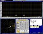
The switch, I guess it is not a ideal 50 Ohm transmission and neither the load behind it, at least not if measured. To reduce losses in your system to a minimum, measure S11 in both directions and calculate impedance network values from that, or let a measurement software do that calculation automatically. Below is pure 50 & 100 Ohm load assumed but it is no problem to insert frequency irregular complex impedance values and still find best possible network solution.

match50-100.jpg

Did read your message once more, attached schematic is for 50->100 Ohm seen from antenna and it was maybe no antenna involved, if so, replace my schematic antenna with a black box, and if you want opposite impedance conversion direction, just mirror the network.
 
Last edited:

Status
Not open for further replies.

Similar threads

Part and Inventory Search

Welcome to EDABoard.com

Sponsor

Back
Top